Concept explainers
Videos
All the problems solutions must include FBD’s.
R5-1. Determine the force in each member of the truss and state if the members are in tension or compression.
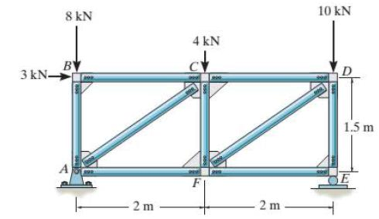
Prob. R5-1
Find the force in each member of truss and the state of members are in tension or compression.
Answer to Problem 1RP
The magnitudes and the state of members are as follows:
- The magnitude of force in the member EF is
- The magnitude of force in the member ED is
- The magnitude of force in the member DF is
- The magnitude of force in the member CD is
- The magnitude of force in the member CF is
- The magnitude of force in the member AF is
- The magnitude of force in the member AC is
- The magnitude of force in the member BC is
- The magnitude of force in the member AB is
Explanation of Solution
Calculation:
Find the reactions.
Show the free body diagram of the truss as in Figure (1).
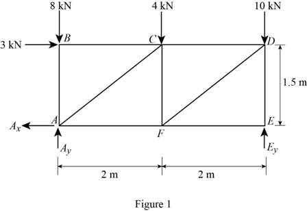
Using Figure (1):
Take moment at joint A and equate to zero.
Along the vertical direction:
Determine the vertical reaction at the joint A by resolving the vertical component of forces.
Substitute 13.125 kN for
Along the horizontal direction:
Determine the horizontal reaction at the joint A by resolving the horizontal component of forces.
Joint E:
Show the free body diagram of the Joint E in Figure (2).
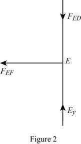
Along the vertical direction:
Determine the force in the member ED by resolving the vertical component of forces.
Along the horizontal direction:
Determine the force in the member EF by resolving the horizontal component of forces.
Thus, the magnitude of force in the member EF is
Conclusion:
Substitute 13.125 kN for
Thus, the magnitude of force in the member ED is
Joint D:
Show the free body diagram of the Joint D in Figure (3).
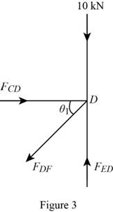
Using Figure (3),
Determine the value of
Substitute 1.5 m for opposite side and 2 m for adjacent side in Equation (3).
Along the vertical direction:
Determine the force in the member DF by resolving the vertical component of forces.
Along the horizontal direction:
Determine the force in the member CD by resolving the horizontal component of force.
Show the calculation of force in the members as follows.
Conclusion:
Substitute 13.125 kN for
Thus, the magnitude of force in the member DF is
Substitute 5.21 kN for
Thus, the magnitude of force in the member CD is
Joint F:
Show the free body diagram of the Joint F in Figure (4).
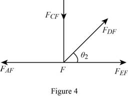
Using Figure (4),
Substitute 1.5 m for opposite side and 2 m for adjacent side in Equation (3).
Along the vertical direction:
Determine the force in the member CF by resolving the vertical component of forces.
Along the horizontal direction:
Determine the force in the member AF by resolving the horizontal component of forces.
Show the calculation of force in the members as follows:
Conclusion:
Substitute 5.21 kN for
Thus, the magnitude of force in the member CF is
Substitute 0 for
Thus, the magnitude of force in the member AF is
Joint C:
Show the free body diagram of the Joint C in Figure (5).
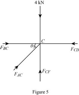
Using Figure (5),
Substitute 1.5 m for opposite side and 2 m for adjacent side in Equation (3).
Along the vertical direction:
Determine the force in the member AC by resolving the vertical component of forces.
Along the horizontal direction:
Determine the force in the member BC by resolving the horizontal component of force.
Conclusion:
Substitute
Thus, the magnitude of force in the member AC is
Substitute 4.17 kN for
Thus, the magnitude of force in the member BC is
Joint B:
Show the free body diagram of the Joint B in Figure (6).
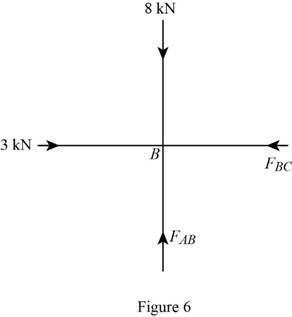
Using Figure (6):
Along the vertical direction:
Determine the force in the member AB by resolving the vertical component of forces.
Thus, the magnitude of force in the member AB is
Want to see more full solutions like this?
Chapter 5 Solutions
Mastering Engineering with Pearson eText -- Standalone Access Card -- for Statics and Mechanics of Materials


- Using the method of joints, determine the force in each member of the truss and state if the members are in tension or compression. Show step by step. P1 = 50 lb, P2 = 90 lb, P3 = 80 lb.arrow_forwardDetermine the force in each member of the loaded truss. The forces are positive if in tension, negative if in compression.Assume F = 2910 N, a = 1.8 m, b = 3.6 m, θ= 40°.arrow_forwardUsing the attached image, determine the force in each member of the truss and state if the members are in tension or compression. Set P1= 2 kN and P2= 1.5 kN. Use method of joint.arrow_forward
- Determine the force developed in the member BC and reactions at the pin support A. Take G1 = 5Kg .arrow_forwardDetermine the tension developed in cables OD and OB and the strut OC, required to support the 50-kg crate. The spring OA has an unstretched length of 0.8 m and stiffness kOA = 1.2 kN/m The force in the strut acts along the axis of the strut.arrow_forwardDetermine the force in member BE. State whether the member is in tension or compression. Set P = 10 kN.arrow_forward
- Determine the force in each member of the truss and state if the members are in tension or compression.Set P1=9kN , P2=15kN.Using the principle of static equilibrium of moments.arrow_forwardDetermine the force in each member of the truss and state if the members are in tension or compression. Set P1 = 10 kN and P2 = 4 kN. (hint: method of joints)arrow_forwardFind the force in member AB of the truss and indicate whether it is in Tension or Compression, given: F = 35 lbs, θ = 46 °arrow_forward
- Each cord can sustain a maximum tension of 200N. Determine the largest weight of sack that can be supported. Also determine angle of cord DC for equilibrium.arrow_forwardThe mobile crane is symmetrically supported by two outriggers at A and B to relieve the suspension of the vehicle on which it sits and to provide extra stability. Determine the vertical reactions at each of the two outriggers as a function of boom angle when the boom is carrying a 1.2 Mg load and the crane and truck have a combined mass of 18 Mg and the boom has a mass of 2 Mg. 0 = 45°arrow_forwardDetermine the force in each member of the double scissors truss in terms of the load P and state if the members are in tension or compression. Use joints method. P=20Km, L=3marrow_forward
 Elements Of ElectromagneticsMechanical EngineeringISBN:9780190698614Author:Sadiku, Matthew N. O.Publisher:Oxford University Press
 Mechanics of Materials (10th Edition)Mechanical EngineeringISBN:9780134319650Author:Russell C. HibbelerPublisher:PEARSON
 Thermodynamics: An Engineering ApproachMechanical EngineeringISBN:9781259822674Author:Yunus A. Cengel Dr., Michael A. BolesPublisher:McGraw-Hill Education
 Control Systems EngineeringMechanical EngineeringISBN:9781118170519Author:Norman S. NisePublisher:WILEY
 Mechanics of Materials (MindTap Course List)Mechanical EngineeringISBN:9781337093347Author:Barry J. Goodno, James M. GerePublisher:Cengage Learning
 Engineering Mechanics: StaticsMechanical EngineeringISBN:9781118807330Author:James L. Meriam, L. G. Kraige, J. N. BoltonPublisher:WILEY