
Concept explainers
Videos
For the problem specified in the table, build upon the results of the original problem to determine the minimum factor of safety for yielding. Use both the maximum-shear-stress theory and the distortion-energy theory, and compare the results. The material is 1018 CD steel.

3–68* to 3–71*
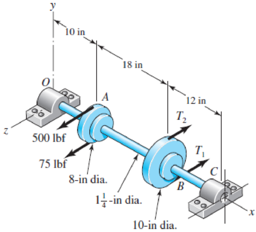
A countershaft carrying two V-belt pulleys is shown in the figure. Pulley A receives power from a motor through a belt with the belt tensions shown. The power is transmitted through the shaft and delivered to the belt on pulley B. Assume the belt tension on the loose side at B is 15 percent of the tension on the tight side.
(a) Determine the tensions in the belt on pulley B, assuming the shaft is running at a constant speed.
(b) Find the magnitudes of the bearing reaction forces, assuming the bearings act as simple supports.
(c) Draw shear-force and bending-moment diagrams for the shaft. If needed, make one set for the horizontal plane and another set for the vertical plane.
(d) At the point of maximum bending moment, determine the bending stress and the torsional shear stress.
(e) At the point of maximum bending moment, determine the principal stresses and the maximum shear stress.
Problem 3–68*
The factor of safety for yielding from maximum-shear-stress theory.
The factor of safety for yielding from distortion-energy theory.
Answer to Problem 39P
The factor of safety for yielding from maximum-shear-stress theory is
The factor of safety for yielding from distortion-energy theory is
Explanation of Solution
The Free body diagram of pulley
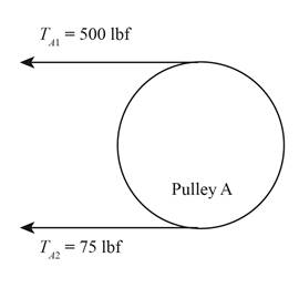
Figure-(1)
The free body diagram of pulley
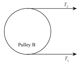
Figure-(2)
The given assumption is that the belt tension on the loose side at
Write the relationship between tension on the loose side with respect to tension on the tight side.
Here, the tension on the loose side is
Write the equation to balance the tension on the counter shaft.
Here, the tension on the tight side of pulley
Substitute
Write the tension on the loose side.
Write the magnitude of bearing reaction force at
Here, the magnitude of the bearing force at
Write the magnitude of bearing reaction force at
Here, the magnitude of bearing reaction force at
Write the shear force at
Here, the shear force at
Write the shear force at
Here, the shear force at
Write the shear force at
Here, the shear force at
Write the shear force at
Here, the shear force at
We know that, the moment at the supports of the simply supported beam is zero.
Write the moment at
Here, the moment at
Write the moment at
Here, the moment at
Write the moment at
Here, the moment at
It is clear from the shear force diagram and bending moment diagram of the shaft that the point of maximum bending moment is at
Write the torque acting at pulley
Here, the torque acting on pulley
Write the bending stress.
Here, the bending stress is
Write the shear stress.
Here, the shear stress is
Write the maximum principal stress.
Here, the maximum principal stress is
Calculate the minimum principal stress.
Here, the minimum principal stress is
Write the maximum shear stress.
Here, maximum shear stress is
Calculate the factor of safety from maximum-shear-stress theory.
Here, the maximum yield stress for
Calculate the factor of safety from distortion-energy theory.
Here, the Von Mises stress is
Write the expression for von Mises stress.
Substitute
Conclusion:
Substitute
Substitute
Substitute
Substitute
Substitute
Substitute
Substitute
Substitute
Substitute
Substitute
The shear force diagram and bending moment diagram for the shaft is as follows.
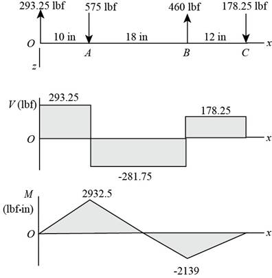
Figure-(3)
Substitute
Substitute
Substitute
Substitute
Substitute
Substitute
Refer to the Table A-20 “Deterministic ASTM Minimum Tensile and Yield Strengths for Some Hot-Rolled (HR) and Cold-Drawn (CD) Steels” to obtain the yield strength of
Substitute
Thus, the factor of safety for yielding from maximum-shear-stress theory is
Substitute
Thus, the factor of safety for yielding from distortion-energy theory is
Want to see more full solutions like this?
Chapter 5 Solutions
Shigley's Mechanical Engineering Design (McGraw-Hill Series in Mechanical Engineering)


- Two sections of steel drill pipe, joined by bolted flange plates at Ä are being tested to assess the adequacy of both the pipes. In the test, the pipe structure is fixed at A, a concentrated torque of 500 kN - m is applied at x = 0.5 m, and uniformly distributed torque intensity t1= 250 kN m/m is applied on pipe BC. Both pipes have the same inner diameter = 200 mm. Pipe AB has thickness tAB=15 mm, while pipe BC has thickness TBC= 12 mm. Find the maximum shear stress and maximum twist of the pipe and their locations along the pipe. Assume G = 75 GPa.arrow_forwardSolve the preceding problem if the thickness of the steel plate is. t = 12 mm. the gage readings are x = 530 × 10-6 (elongation) and y = -210 -× l0-6 (shortening), the modulus is E = 200 GPa, and Poisson’s ratio is v = 0.30.arrow_forwardThree round, copper alloy bars having the same length L but different shapes are shown, in the figure. The first bar has a diameter d over its entire length, the second has a diameter d over one-fifth of its length, and the third has a diameter d over one-fifteenth of its length. Elsewhere, the second and third bars have a diameter Id. All three bars are subjected to the same axial load P. Use the following numerical data: P = 1400 kN, L = 5m,d= 80 mm, E= 110 GPa. and v = 0.33. (a) Find the change in length of each bar. (b) Find the change in volume of each bar.arrow_forward
- Bar of steel, (yield strenght Sy = 462 MPa) is subjected to the following stresses; σx = 171 MPa , σy = -144 MPa , τxy = 175 MPa Using the Distortion-Energy Theory determine the factor of safety and check is the bar will fail or not.arrow_forwardB).shear stress caused by T C).APply miaximum-Distortion-energy Theory and calculate Mises equivalent stress. Enter your answer in MPa to 2 decimal places. D). determine factor of safety n (upto 2 decimal places)arrow_forwarda)Normal stress due to bending caused by V. Enter your answer in MPa b) Shear stress caused by T. Enter your answer in MPa c) Apply the Maximum-Distortion-Energy Theory and calculate Mises equivalent stress. Enter your answer in MPa d) Determine the factor of safety n.arrow_forward
- The material of a certain transmission shaft uses AISI 1030 HR, its yield strength is 260 MPa, the transmission torque of this shaft is 160 N·m, and it is subjected to a uniform axial tension of 0.5 kN. Please calculate according to the Distortion energy theory. The minimum shaft diameter with a safety factor n of 2.5 (to 2 decimal places).arrow_forwardThe three principal stresses at a given point are σ1 =60 MPa, σ2 =−100 MPa, σ3 =−10 MPa. If the material has a yield stress of 250 MPa, estimate the factor of safety against yielding using (i) the maximum shear stress theory and (ii) von Mises’ theory.arrow_forwardOn the figure shown, a ring which is supported by the spring, is subjected to a concurrent forces P1 = 2000 N, and P2 = 2500 N. The ring is being kept in an equilibrium state by the spring attached. Determine the shearing stress of the spring (using the first equation) if the mean radius is 100 mm, G = 30 GPa, number of turns is 10, and diameter of the spring is 10 mm. Also, determine the deformation of the spring.Show complete solution with FBDarrow_forward
- A shaft made of steel receives 7.5 kW power at 1500 rpm. A pulley mounted on the shaft as shown in Fig. has ratio of belt tensions 4. The gear forces are as follows: Ft = 1590 N; Fr=580 N Designe the shaft diameter by maximum shear stress theory. The shaft material has the following properties: Ultimate tensile strength = 720 MPa: Yield strength = 380 MPa: Factor of safety = 1.5arrow_forwardThe factors of safety at point H predicted by the maximum-distortion-energy theory (von Mises criterion) can be calculated as The von Mises equivalent stresses at point H can be calculated as MPaarrow_forwardA shaft is loaded by a torque of 5 KN-m. The material has a yield point of350 MPa. Find the required diameter using(a) Maximum shear stress theory(b) Maximum distortion energy theoryTake a factor of safety of 2.5.arrow_forward
 Mechanics of Materials (MindTap Course List)Mechanical EngineeringISBN:9781337093347Author:Barry J. Goodno, James M. GerePublisher:Cengage Learning