
Concept explainers
Videos
For the problem specified in the table, build upon the results of the original problem to determine the minimum factor of safety for yielding. Use both the maximum-shear-stress theory and the distortion-energy theory, and compare the results. The material is 1018 CD steel.


3–72* to 3–73*
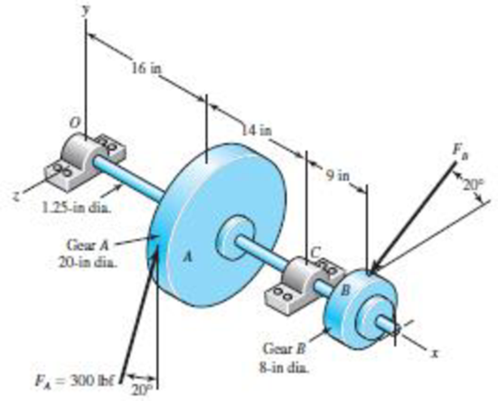
A gear reduction unit uses the countershaft shown in the figure. Gear A receives power from another gear with the transmitted force FA applied at the 20° pressure angle as shown. The power is transmitted through the shaft and delivered through gear B through a transmitted force FB at the pressure angle shown.
(a) Determine the force FB, assuming the shaft is running at a constant speed.
(b) Find the bearing reaction forces, assuming the bearings act as simple supports.
(c) Draw shear-force and bending-moment diagrams for the shaft. If needed, make one set for the horizontal plane and another set for the vertical plane.
(d) At the point of maximum bending moment, determine the bending stress and the torsional shear stress.
(e) At the point of maximum bending moment, determine the principal stresses and the maximum shear stress.
The factor of safety for yielding from distortion-energy theory.
The factor of safety for yielding from maximum-shear-stress theory.
Answer to Problem 43P
The factor of safety for yielding from distortion-energy theory is
The factor of safety for yielding from maximum-shear-stress theory is
Explanation of Solution
The figure below shows the free body diagram of pulley A.
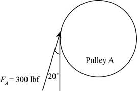
Figure (1)
The figure below shows the free body diagram of pulley B.
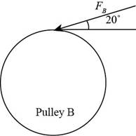
Figure (2)
Calculate the force
Here, the force acting on pulley
Write the moment about bearing
Here, the reaction force at bearing
Write the equation to balance the forces in
Here, the reaction force at bearing
Write the moment about bearing
Here, the reaction force at bearing
Write the equation to balance the forces in
Here, the reaction force at bearing
Calculate the reaction forces at bearing
Here, the reaction force at bearing
Calculate the reaction forces at bearing
Here, the reaction force at bearing
The calculations for shear force and bending moment diagram in
Calculate the shear force at
Here, the shear force at
Calculate the shear force at
Here, the shear force at
Calculate the shear force at
Here, the shear force at
Calculate the shear force at
Here, the shear force at
Calculate the moment at
Here, the moment at
Calculate the moment at
Here, the moment at
Calculate the moment at
Here, the moment at
Write the net moment at
Here, the net moment at
Write the net moment at
Here, the net moment at
Write the torque transmitted by shaft from
Here, the torque transmitted by shaft from
Calculate the bending stress.
Here, the bending stress is
Calculate the shear stress.
Here, the shear stress is
Calculate the maximum principal stress.
Here, the maximum principal stress is
Calculate the minimum principal stress.
Here, the minimum principal stress is
Calculate the maximum shear stress.
Here, maximum shear stress is
Calculate the factor of safety from maximum-shear-stress theory.
Here, the maximum yield stress for
Calculate the factor of safety from distortion-energy theory.
Here, the Von Mises stress is
Write the expression for von Mises stress.
Substitute
Conclusion:
Substitute
Thus, the force
Substitute
Substitute
Substitute
Substitute
Substitute
Substitute
Substitute
Substitute
Substitute
Substitute
Substitute
Substitute
The shear force and bending moment diagram in
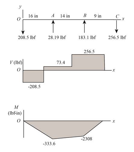
Figure-(3)
Substitute
Substitute
Substitute
Substitute
Substitute
Substitute
Thus, the shear force and bending moment diagram in
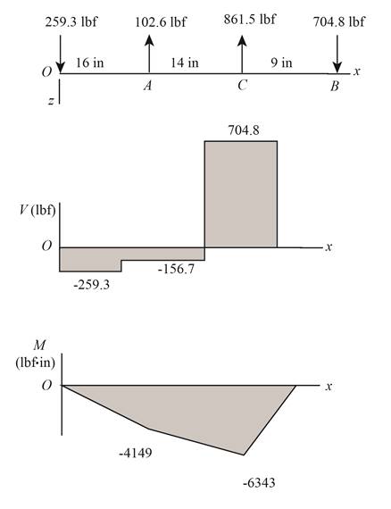
Figure-(4)
Substitute
Substitute
Since,
Substitute
Substitute
Thus, the bending stress at point of maximum bending moment is
Substitute
Substitute
Substitute
Substitute
Refer to the Table A-20 “Deterministic ASTM Minimum Tensile and Yield Strengths for Some Hot-Rolled (HR) and Cold-Drawn (CD) Steels” and obtain the yield strength as
Substitute
Thus, the factor of safety for yielding from maximum-shear-stress theory is
Substitute
Thus, the factor of safety for yielding from distortion-energy theory is
Want to see more full solutions like this?
Chapter 5 Solutions
Shigley's Mechanical Engineering Design (McGraw-Hill Series in Mechanical Engineering)


- In the fabric dye-printing system given in the figure, the motion is transmitted from the electric motor to the drum of the machine. There is a two-stage reducer in between. Number of teeth of gears z1=17; z2=85; z3=18; z4=72; The efficiency of a pair of gears is given as na=0.97 and the efficiency of each of the gearbox shafts and lower bearing pairs to the drum bearing is given as n=0.97. The diameter of the drum will be D=200 mm, the fabric speed will be v=1 m/s and the pulling force required to activate the band will be taken as F-2000 N. a) Find the number of revolutions of the engine. b) Find the required engine power.arrow_forwardThe figure (attached) shows a belt pulley mechanism which is loaded statically. The shaft is made of AISI 1030 steel with the yield strength of 480 MPa. Using distortion energy theory (DET), determine the diameter of the shaft with a factor of safety of 2.arrow_forwardA Steel shaft is subjected to an end thrust producing a stress of 90 MPa and the minimum shearing stress on the surface arising from torsion is 60 MPa .The yield point stress of the material in simple tension was found to be 300 MPa. calculate the factor of safety of the shaft according to the following theory 1)maximum shear stress theoryarrow_forward
- Torque in = 40nm Holding torque out = 896nm 8.Using your answers from the gear box above, and given that the input shaft has a diameter of 12 mm and the output shaft has a diameter of 15 mm, both shafts are made from aluminium. When this transmission system was operated, it failed. Identify the position where the failure occurred and the reason for this failure. Suggests improvements to the system to overcome the failure mode. The shear strength of aluminium is 207 MPa.arrow_forwardThe material of a certain transmission shaft uses AISI 1030 HR, its yield strength is 260 MPa, the transmission torque of this shaft is 160 N·m, and it is subjected to a uniform axial tension of 0.5 kN. Please calculate according to the Distortion energy theory. The minimum shaft diameter with a safety factor n of 2.5 (to 2 decimal places).arrow_forwardAs seen in the figure, a construction machine is rotated by a drive mechanism consisting of belt-pulley and spur gear mechanisms. Engine power P = 5.5 kW ; engine shaft speednm = 1500 rpm ; drive pulley diameter Dt = 16 cm ; diameter of the opposite pulley Dk = 55 cm ; number of pinion teeth z1 = 21 ; number of teeth of the counter gearz2 = 60 ; pulley mechanism efficiency ηk = 0.95 ; Since the efficiency of the gear mechanism is ηd = 0.97: a) Find the output shaft speed nç and the torque Mç on this shaft.b) The force on the taut arm of the belt S1 = 450 N;coefficient of friction μ = 0.3 ; If the winding angle α = 160⁰, is the frictionally transmitted moment Ms sufficient to compensate for the Mg moment on the input shaft? Calculate.arrow_forward
- The motor shown in the figure supplies 16.5 kW at 1540 rpm at A. Shafts (1) and (2) are each solid 28 mm diameter shafts. Shaft (1) is made of an aluminum alloy [ G=26 GPa], and shaft (2) is made of bronze [ G=45 GPa]. The shaft lengths are L1=3.3m and L2=2.9m, respectively. Gear B has 56 teeth, and gear C has 97 teeth. The bearings shown permit free rotation of the shafts. Determine: the rotation angle of gear D with respect to flange A. [Answer φD/A = 0.314 rad]arrow_forwardIn the design in the figure, a force of Fn=45992 N acts in the vertical plane on a machine element with a diameter of D=200 mm on the shaft resting on the A and B bearings. If the angle made by this force with the horizontal is b=40o, find the life of the 6210 coded Deep Ball bearing to be used in the B bearing, in hours. Number of revolutions = 30 rpm. 1-) The diameter of the machine element on which the force acts will be taken into account in the calculation of bearing forces (That is, it will be assumed that the Fn force AFFECTS THE GROUND shown in the figure, NOT the axis of the shaft). 2-) Pi number will be taken as 3.14.arrow_forwardThe intermediate shaft of a two-stage gearbox is given in the figure. P = 4 kW power is transmitted at n = 150 rpm with the help of two helical gears on the shaft.The forces acting on the gears are given as Ft1 = 5092 N, Fr1 = 1972 N, Fa1 = 1853 N, Ft2 = 2546 N, Fr2 = 986 N, Fa2 = 926 N. Diameter of small helical gear d1 = 100 mm, largethe diameter of the gear is d2 = 200 mm. Shaft material yield strength 335 MPa, tensile strength 600 MPa, Kç = 1.95, ka = 0.895, kb = 0.90 and safety coefficient = 1.4now thatarrow_forward
- A shaft is loaded by a torque of 5 KN-m. The material has a yield point of350 MPa. Find the required diameter using(a) Maximum shear stress theory(b) Maximum distortion energy theoryTake a factor of safety of 2.5.arrow_forwardA short stub shaft, made of SAE 1035, as rolled, receivers 30 hp at 300 rpm via a 12-in. spur gear, the power being delivered to another shaft through a flexible coupling. The gear is keyed (profile keyway) midway between the bearings. The pressure angle of the gear teeth 20o, N = 1.5 based on the octahedral shear stress theory with varying stresses. (a) Neglecting the radial component R of the tooth load W , determine the shaft diameter. (b) Considering both the tangential and the radial components, compute the shaft diameters. (c) Is the difference in the results of the parts (a) and (b) enough to change your choice of the shaft size?arrow_forwardThe shaft shown in the figure is machined from AISI 1040 CD steel. The shaft rotates at 1600 rpm and is supported in rolling bearings at A and B. The applied forces are F1 = 1600 lbf and F2 = 640 lbf. A steady torque of 1600 lbf·in is being transmitted through the shaft between the points of application of the forces. ——————————————- Determine the endurance limit for this material as well as the value after correction for surface finish, sizing, and loading. (You must provide an answer before moving to the next part.) The endurance limit for this material is kpsi. The value after correction for surface finish, sizing, and loading is kpsi.arrow_forward
 Mechanics of Materials (MindTap Course List)Mechanical EngineeringISBN:9781337093347Author:Barry J. Goodno, James M. GerePublisher:Cengage Learning