
Videos
-1 through 5.10-6 A wide-flange beam (see figure) is subjected to a shear force V. Using the dimensions of the cross section, calculate the moment of inertia and then determine the following quantities:
- The maximum shear stress tinixin the web.
Note: Disregard the fillets at the junctions of the web and flanges and determine all quantities, including the moment of inertia, by considering the cross section to consist of three rectangles.
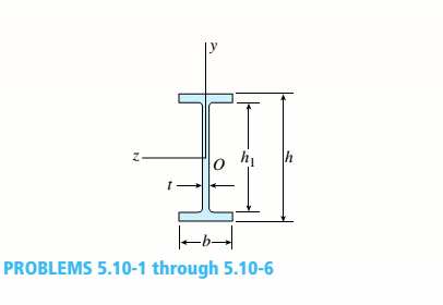
5.10-4 Dimensions of cross section: b = 220 mm, f = 12 mm, h = 600 mm, hx= 570 mm, and V = 200 kN.
(a).
To Find:
The moment of inertia and the maximum shear stress in the web.
Answer to Problem 5.10.4P
The maximum shear stress in the web is
Explanation of Solution
Given Information:
Shear Force
Dimensions:
Concept Used:
Following formula will be used:
Maximum shear stress,
Moment of inertia of rectangle,
Calculation:
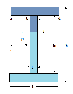
Area of upper and lower flanges/rectangles:

Second rectangle is
In which
The first moment of areas of
By putting the values of
The moment of inertia for the I section is given by following formula:
The maximum value of shear stress will be at neutral axis when
Conclusion:
The maximum shear stress in the web is
(b).
To Find:
The minimum shear stress in web.
Answer to Problem 5.10.4P
The minimum shear stress in the web is
Explanation of Solution
Given Information:
Shear Force
Dimensions:
Concept Used:
Following formula will be used:
Minimum shear stress,
Calculation:
Area of upper and lower flanges:
Second rectangle is
In which
The first moment of areas of
By putting the values of
The moment of inertia for the I section is given by following formula:
The minimum value of shear stress will be at
Conclusion:
The minimum shear stress in the web is
(c).
To Find:
The average shear stress in web.
Answer to Problem 5.10.4P
The average shear stress in the web is
Explanation of Solution
Given Information:
Shear Force
Dimensions,
Concept Used:
Following formula will be used:
Average shear stress,
Calculation:
The average shear stress in the web is:
Conclusion:
The average shear stress in the web is
(d).
To Find:
Shear force
Answer to Problem 5.10.4P
Shear force in the web is
Explanation of Solution
Given Information:
Shear Force
Dimensions:
Concept Used:
Following formula will be used:
Shear stress in the web,
Calculation:
Shear stress in the web:
Conclusion:
Shear force in the web is
Want to see more full solutions like this?
Chapter 5 Solutions
Mechanics of Materials (MindTap Course List)


- -1 through 5.10-6 A wide-flange beam (see figure) is subjected to a shear force V. Using the dimensions of the cross section, calculate the moment of inertia and then determine the following quantities: The maximum shear stress tinixin the web. The minimum shear stress rmin in the web. The average shear stress raver (obtained by dividing the shear force by the area of the web) and the ratio i^/t^ The shear force carried in the web and the ratio V^tV. Noie: Disregard the fillets at the junctions of the web and flanges and determine all quantities, including the moment of inertia, by considering the cross section to consist of three rectangles. 5.10-3 Wide-flange shape, W 8 x 28 (see Table F-L Appendix F); V = 10 karrow_forward-1 through 5.10-6 A wide-flange beam (see figure) is subjected to a shear force V. Using the dimensions of the cross section, calculate the moment of inertia and then determine the following quantities: The maximum shear stress tinixin the web. The minimum shear stress rmin in the web. The average shear stress raver (obtained by dividing the shear force by the area of the web) and the ratio i^/t^. The shear force i^/t^ carried in the web and the ratio V^tV. Note: Disregard the fillets at the junctions of the web and flanges and determine all quantities, including the moment of inertia, by considering the cross section to consist of three rectangles. 5.10-6 Dimensions of cross section: b = 120 mm, a = 7 mm, h = 350 mm, hx= 330 mm, and K=60kN.arrow_forward-1 through 5.10-6 A wide-flange beam (see figure) is subjected to a shear force V. Using the dimensions of the cross section, calculate the moment of inertia and then determine the following quantities: The maximum shear stress tinixin the web. The minimum shear stress rmin in the web. The average shear stress raver (obtained by dividing the shear force by the area of the web) and the ratio i^/t^ The shear force carried in the web and the ratio K b/K. Note: Disregard the fillets at the junctions of the web and flanges and determine all quantities, including the moment of inertia, by considering the cross section to consist of three rectangles. 5.10-2 Dimensions of cross section: b = 180 mm, v = 12 mm, h = 420 mm, i = 380 mm, and V = 125 kN.arrow_forward
- A beam of square cross section (a = length of each side) is bent in the plane of a diagonal (see figure). By removing a small amount of material at the top and bottom corners, as shown by the shaded triangles in the figure, you can increase the section modulus and obtain a stronger beam, even though the area of the cross section is reduced. Determine the ratio ß defining the areas that should be removed in order to obtain the strongest cross section in bending. By what percent is the section modulus increased when the areas arc removed?arrow_forwardA steel beam of length L = 16 in. and cross-sectional dimensions h = 0.6 in. and h = 2 in. (see figure) supports a uniform load of intensity if = 240 lb/in., which includes the weight of the beam. Calculate the shear stresses in the beam (at the cross section of maximum shear force) at points located 1/4 in., 1/2 in., 3/4 in., and I in, from the top surface of the beam. From these calculations, plot a graph showing the distribution of shear stresses from top to bottom of the beam.arrow_forwardA beam of wide-flange shape, W 8 x 28, has the cross section shown in the figure. The dimensions are b = 6.54 in., h = 8.06 in., fw = 0.285 in., and tf = 0.465 in.. The loads on the beam produce a shear force V = 7.5 kips at the cross section under consideration. Use center line dimensions to calculate the maximum shear stress raiaxin the web of the beam. Use the more exact analysis of Section 5,10 in Chapter 5 to calculate the maximum shear stress in the web of the beam and compare it with the stress obtained in part .arrow_forward
- -1 through 5.10-6 A wide-flange beam (see figure) is subjected to a shear force V. Using the dimensions of the cross section, calculate the moment of inertia and then determine the following quantities: The maximum shear stress tinixin the web. The minimum shear stress rmin in the web. The average shear stress raver (obtained by dividing the shear force by the area of the web) and the ratio i^/t^ The shear force carried in the web and the ratio V^tV. Note: Disregard the fillets at the junctions of the web and flanges and determine all quantities, including the moment of inertia, by considering the cross section to consist of three rectangles. 5.10-5 Wide-flange shape, W 18 x 71 (sec Table F-l, Appendix F); V = 21 k.arrow_forwardA simple beam of span length 3.2 m carries a uniform load of intensity 48 kN/m, The cross section of the beam is a hollow box with wood flanges and steel side plates, as shown in the figure. The wood flanges are 75 mm x 100 mm in cross section, and the steel plates are 300 mm deep. What is the required thickness t of the steel plates if the allowable stresses are 120 M Pa for the steel and 6,5 M Pa for the wood? (Assume that the moduli of elasticity for the steel and wood are 210 GPa and 10 GPa, respectively, and disregard the weight of the beam.)arrow_forwardA composite beam consisting of fiberglass faces and a core of particle board has the cross section shown in the figure. The width of the beam is 2,0 in., the thickness of the faces is 0,10 in., and the thickness of the core is 0.50 in. The beam is subjected to a bending moment of 250 lb-in, acting about the - axis. Find the maximum bending stresses tr(and ctc in the faces and the core, respectively, if their respective moduli of elasticity are 4 x 10⁶ psi and 1.5 x 10⁶ psi.arrow_forward
- A cantilever beam AB having rectangular cross sections with varying width bxand varying height hxis subjected to a uniform load of intensity q (sec figure). If the width varies linearly with x according to the equation hx= bBxiL^ how should the height hxvary as a function of v in order to have a fully stressed beam? (Express hxin terms of the height hBat the fixed end of the beam.)arrow_forwardA wood beam reinforced by an aluminum channel section is shown in the figure. The beam has a cross section of dimensions 150 mm x 250 mm, and the channel has a uniform thickness of 6.5 mm. If the allowable stresses in the wood and aluminum are 8 M Pa and 38 M Pa, respectively, and if their moduli of elasticity are in the ratio 1 to 6, what is the maximum allowable bending moment for the beam?arrow_forwardA beam with a channel section is subjected to a bending moment M having its vector at an angle 0 to the 2 axis (see figure). Determine the orientation of the neutral axis and calculate the maximum tensile stress et and maximum compressive stress ecin the beam. Use the following data: C 8 × 11.5 section, M = 20 kip-in., tan0=l/3. See Table F-3(a) of Appendix F for the dimensions and properties of the channel section.arrow_forward
 Mechanics of Materials (MindTap Course List)Mechanical EngineeringISBN:9781337093347Author:Barry J. Goodno, James M. GerePublisher:Cengage Learning