
(a)
Whether a
Answer to Problem 5.15.6P
Adequate
Explanation of Solution
Given:
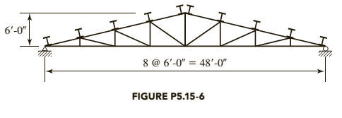
Total gravity load = 40 psf of roof surface

Formula used:
Lpis unbraced length in an inelastic behavior
Lris unbraced length in an elastic behavior
Mn is nominal moment strength
Mpis plastic moment capacity
Calculation:
Determine the nominal flexural strength about x and y axes:
Neither the beam design charts nor the Z tables include shapes smaller than W8, so the flexural strength of the
From the dimensions and properties tables, the shape is compact.
The following properties of a
A is Cross-sectional area
Sxis Elastic section modulus about X -axis
Zxis Plastic section modulus about X -axis
Iyis Moment of inertia about Y -axis
ryis Radius of gyration about Y -axis
Syis Elastic section modulus about Y -axis
Cwis Warping constant
h0is Distance between centroid of flanges
J is Torsional moment of inertia
For
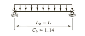
From the below given figure in the textbook,

For the y axis, since the shape is compact, there is no flange local buckling
Check the upper limit:
Roof load: Combination 3 controls
where,D is dead load and S is snow load

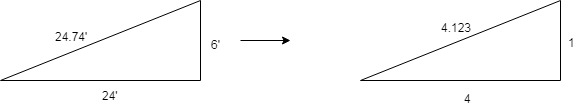
Tributary width =
Purlin load =
Component normal to roof =
Component parallel to roof =
Calculate factored bending moment about x axis and y axis
Use ½ of weak-axis bending strength in the interaction equation:
Conclusion:
(b)
Whether a
Answer to Problem 5.15.6P
Adequate
Explanation of Solution
Given:
Total gravity load = 40 psf of roof surface
Formula used:
Lpis unbraced length in an inelastic behavior
Lris unbraced length in an elastic behavior
Mn is nominal moment strength
Mpis plastic moment capacity
Calculation:
Determine the nominal flexural strength about x and y axes:
Neither the beam design charts nor the Z tables include shapes smaller than W8, so the flexural strength of the
From the dimensions and properties tables, the shape is compact.
The following properties of a
A is Cross-sectional area
Sxis Elastic section modulus about X -axis
Zxis Plastic section modulus about X -axis
Iyis Moment of inertia about Y -axis
ryis Radius of gyration about Y -axis
Syis Elastic section modulus about Y -axis
Cwis Warping constant
h0is Distance between centroid of flanges
J is Torsional moment of inertia
For
From the below given figure in the textbook,
For the y axis, since the shape is compact, there is no flange local buckling
Check the upper limit:
Roof load: Combination 3 controls
where, D is dead load and S is snow load
Tributary width =
Purlin load =
Component normal to roof =
Component parallel to roof =
Calculate factored bending moment about x axis and y axis
Use ½ of weak - axis bending strength in the interaction equation:
Conclusion:
Want to see more full solutions like this?
Chapter 5 Solutions
Steel Design (Activate Learning with these NEW titles from Engineering!)

- Q) Determine the elastic and plastic moment of resistance of the RC beam. The beam is a trapezoid in shape. B1 at top = 300mm, B2 at bottom = 500mm, total height = 600mm, height from top to the bottom of the steel reinforcement = 570mm, As = 1473mm^2, Fy=350MPa, Fcu=30MPa Solve this early I upvotearrow_forwardA W610 x 82 beam of A 36 steel has end reaction of 309 kN and is supported on a plate with a length of bearing of 154 mm. Fy = 248 MPa. Properties: d = 599 mm tw = 11 mm tf = 12.8 mm K = 33.88 Determine the end reaction due to web crippling.arrow_forwardDesign the W14 section column AB of the frame shown. Assume it is unbraced along the x axis andbraced in the weak y direction. The loads on the column are dead load D = 200 kips and live load L = 600kips. First determine the effective length factor K via nomographs. All girders (beams) are W16 × 100.arrow_forward
- Steel Design A W610 x 82 beam of A 36 steel has end reaction of 302 kN and is supported on a plate with a length of bearing of 157 mm. Fy = 248 MPa. Properties: d = 599 mm tw = 10 mm tf = 12.8 mm K = 32.36 If the beam is inadequate with respect to web crippling, determine the length of bearing needed to prevent web crippling at the end reaction. Determine the end reaction due to web crippling.arrow_forwardCheck the adequacy of the column shown in red colour with the 200UC59.5 section. The material is 300 Plus. Dead and live loads for all floors are the same as shown in Figure 1. All the support conditions are shown in the Figure. For bending about the minor axis, y, there is an intermediate secondary member that prevents its buckling and the column is simply supported. In case of buckling about the major axis, x, there is no intermediate lateral support and the column is pinned at the top and fixed at the bottom.arrow_forwardA W12x79 of A573 Grade 60 (Fy = 415 MPa) steel is used as a compression member. It is 8 m long, pinned at the top fixed at bottom with additional lateral support at mid height in the weak direction. The properties are as follows: Ag = 14,500 sq.mm, Ix= 258.6 x10^6 mm ^4 Iy=84.375 x 10^6 mm^4. 59. If the columns sustains a service axial dead load of 1 490 KN Calculate the safe service axial live load in KN by ASD.arrow_forward
- A cantilever beam having a 4m span carries a uniformly distributed load throughout its length. The beam is A36 steel with yield strength Fy = 248 MPa. The beam is not restrained against lateral buckling. The beam is W 21 x 93 steel. Determine the maximum value of the moment at the fixed support. Please include FBD/drawing.arrow_forwardSteel Design Two channels having the given properties shown is placed at a distance of 300 mm to back and is properly connected by a pair of lacings as shown. Properties of one channel A = 5595 mm2 d = 305 mm x = 17mm Ix = 67.3 x 106 mm4 Iy = 2.12 x 106 mm4 rx = 19.3 mm Assume K = 1.0 Determine the safe axial load in kN, that the column section could carry. Unsupported height of column is 6m.arrow_forwardAn A36 channel section is used as a purlin in a roof system with spacing of trusses at 4.5 m apart. Purlins are to be places at the joints and at the mid points of each top chord member. Sag rods are places at the center of each purlin. The total gravity loads consists of a dead load of 1.2 kpa roof surface (including weight of roofing and purlins) and a live load of 1.4 kPa of the roof surface. Assume the steel section is a compact section and that all loads are applied at the top flange of the purlins. Use LRFD method. (Refer to the figure for the value of equal soacing = S) Properties: Sx = 221.28 x 10^3 mm3 Sy = 19.01 x 10^3 mm3 Zx = 258.82 x 10^3 mm3 Zy = 38.51 x 10^3 mm3 Lp = 0.90 m Lr = 3.34 m Cb = 1.30 m Fy = 248 mPa Use LRFD design method. Determine the flexural strength of the purlins about the x-axis. (kN/m)arrow_forward
- P10.10. A W27×94 section of A572 Grade 50 steel 34 feet long, it is used as a simply supported beam. It is subjected to a factored concentrated load of 90 kips at 12 feet from each support. In addition, the beam is subjected to a factored moment of 340 kips-ft at its left end (counterclockwise). Neglect the self-weight of the beam in the calculations, and check whether the beam is safe according to the LRFD. Lateral support is only provided at the ends and load points.arrow_forwardA 290 kg/m light crane rail sits on and is securely fastened to a W400mmx67kg/m crane girder.The girder is simply supported on a span of 9m.Assume full transfer of lateral load to the top flange of the girder. Crane wheel loads: Vertical load at the centroid (V)=80kN Horizontal load at the top flange (H)=8kN Properties: A=8580 mm^2 d=400 mm bf=179 mm tf=14 mm Ix=244 x 10^6 mm^4 Iy=14 x 10^6 mm^4 tw=8.5 mm a.what is the maximum bending stress fbx(MPa) in the girder? b.determine the maximum bending stress fby(MPa) in the girder c.Using the interaction formula fbx/Fbx + fby/Fbyarrow_forwardA steel beam cross cross section is assembled as shown by bolting the channel, C200 x 27.9 through its web on the wide flange, W200 x 35.9. The beam is 4 m span and is simply supported loaded with a uniformly distributed load of intensity 20 kN/m throughout its span and a concentrated load, P kN = 52, at the mid span. If the diameter of the bolts is 22 mm. a) compute for the moment of inertia of the cross section b) determine the minimum bending stress in the beam c) calculate the spacing of bolts (pitch) if the allowable shearing stress for a bolt is 100 MPa. Kindly write legibly. Thank you.arrow_forward
 Steel Design (Activate Learning with these NEW ti...Civil EngineeringISBN:9781337094740Author:Segui, William T.Publisher:Cengage Learning