
Structural Analysis
6th Edition
ISBN: 9781337630931
Author: KASSIMALI, Aslam.
Publisher: Cengage,
expand_more
expand_more
format_list_bulleted
Videos
Textbook Question
Chapter 5, Problem 54P
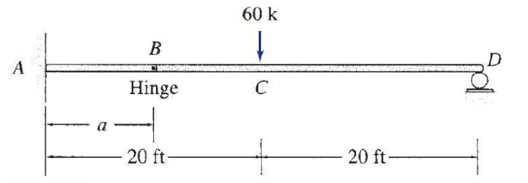
For the beam shown: (a) determine the distance a for which the maximum positive and negative bending moments in the beam are equal; and (b) draw the corresponding shear and bending moment diagrams for the beam.
Expert Solution & Answer

Trending nowThis is a popular solution!

Students have asked these similar questions
For the beam shown: (a) determine the distance “a” for which the maximum positive and negative bending moments in the beam are equal; and (b) draw the corresponding shear and bending moment diagrams for the beam. COMPLETE SOLUTION
The 16ft long cantilevered beam has a fixed support at Point D. the beam is subjected to the loads and moments as shown in the image. Use the static equilibrium method to determine the formulas for shear (V) and moment (M) in each region of the beam.
Determine (a) the equations of the shear and bending-moment curves for the beam and loading shown, (b) the maximum absolute value of the bending moment in the beam
Chapter 5 Solutions
Structural Analysis
Ch. 5 - Prob. 1PCh. 5 - Prob. 2PCh. 5 - Prob. 3PCh. 5 - Prob. 4PCh. 5 - Prob. 5PCh. 5 - Prob. 6PCh. 5 - Prob. 7PCh. 5 - Prob. 8PCh. 5 - Prob. 9PCh. 5 - Prob. 10P
Ch. 5 - Prob. 11PCh. 5 - Determine the equations for shear and bending...Ch. 5 - Determine the equations for shear and bending...Ch. 5 - Determine the equations for shear and bending...Ch. 5 - Determine the equations for shear and bending...Ch. 5 - Determine the equations for shear and bending...Ch. 5 - Determine the equations for shear and bending...Ch. 5 - Determine the equations for shear and bending...Ch. 5 - 5.12 through 5.28 Determine the equations for...Ch. 5 - 5.12 through 5.28 Determine the equations for...Ch. 5 - 5.12 through 5.28 Determine the equations for...Ch. 5 - 5.12 through 5.28 Determine the equations for...Ch. 5 - 5.12 through 5.28 Determine the equations for...Ch. 5 - 5.12 through 5.28 Determine the equations for...Ch. 5 - 5.12 through 5.28 Determine the equations for...Ch. 5 - 5.12 through 5.28 Determine the equations for...Ch. 5 - 5.12 through 5.28 Determine the equations for...Ch. 5 - 5.12 through 5.28 Determine the equations for...Ch. 5 - 5.29 through 5.51 Draw the shear and bending...Ch. 5 - 5.29 through 5.51 Draw the shear and bending...Ch. 5 - 5.29 through 5.51 Draw the shear and bending...Ch. 5 - 5.29 through 5.51 Draw the shear and bending...Ch. 5 - 5.29 through 5.51 Draw the shear and bending...Ch. 5 - 5.29 through 5.51 Draw the shear and bending...Ch. 5 - 5.29 through 5.51 Draw the shear and bending...Ch. 5 - 5.29 through 5.51 Draw the shear and bending...Ch. 5 - 5.29 through 5.51 Draw the shear and bending...Ch. 5 - 5.29 through 5.51 Draw the shear and bending...Ch. 5 - 5.29 through 5.51 Draw the shear and bending...Ch. 5 - 5.29 through 5.51 Draw the shear and bending...Ch. 5 - 5.29 through 5.51 Draw the shear and bending...Ch. 5 - 5.29 through 5.51 Draw the shear and bending...Ch. 5 - 5.29 through 5.51 Draw the shear and bending...Ch. 5 - 5.29 through 5.51 Draw the shear and bending...Ch. 5 - 5.29 through 5.51 Draw the shear and bending...Ch. 5 - 5.29 through 5.51 Draw the shear and bending...Ch. 5 - 5.29 through 5.51 Draw the shear and bending...Ch. 5 - 5.29 through 5.51 Draw the shear and bending...Ch. 5 - 5.29 through 5.51 Draw the shear and bending...Ch. 5 - 5.29 through 5.51 Draw the shear and bending...Ch. 5 - 5.29 through 5.51 Draw the shear and bending...Ch. 5 - Draw the shear and bending moment diagrams for the...Ch. 5 - For the beam shown: (a) determine the distance a...Ch. 5 - For the beam shown: (a) determine the distance a...Ch. 5 - Prob. 55PCh. 5 - Prob. 56PCh. 5 - Prob. 57PCh. 5 - Prob. 58PCh. 5 - Prob. 59PCh. 5 - Prob. 60PCh. 5 - Prob. 61PCh. 5 - Prob. 62PCh. 5 - Prob. 63PCh. 5 - Prob. 64PCh. 5 - Prob. 65PCh. 5 - Prob. 66PCh. 5 - Prob. 67PCh. 5 - Prob. 68PCh. 5 - Prob. 69PCh. 5 - Prob. 70PCh. 5 - Prob. 71P
Knowledge Booster


Learn more about
Need a deep-dive on the concept behind this application? Look no further. Learn more about this topic, civil-engineering and related others by exploring similar questions and additional content below.Similar questions
- Problem 02: Draw the shear and bending-moment diagrams for the beam and loading shown, and determine maximum absolute value of the shear, (b) of the bending moment.arrow_forwardFor the beam and loading shown, (a) write the equations of the shear and bending-moment curves, (b) determine the magnitude and location of the maximum bending moment.arrow_forwardThe beam AC is simply supported at A and C and subject to the uniformly distributed load of 300 N/m plus the couple of magnitude 2700 N ⋅ m as shown in figure. Write the moment equation between A and C. Draw the shear and moment diagram. Determine the maximum shear and flexural stress of the beam with a rectangular cross section of 150mm x 250mm.arrow_forward
- Solve it complete solution! Draw the shear and bending moment diagrams for the beam loaded as shown.arrow_forwardSolve the following problem: The beam AB is subjected to the uniformly distributed load shown in the figure and to two unknown forces P and Q. If it is known that the experimental calculation of the value of the bending moment is 4.5 kip * ft at point D and 3.5 kip * ft at point E. a) Determine P and Q b) Draw the shear force and bending moment diagrams for the beam.arrow_forwardFor the beam and loading shown, determine the absolute values of the shear and bending moment at 4 m to the right of point A.arrow_forward
- A simple beam AB is loaded by two segment of uniform load and two horizontal and vertical forces acting at the ends of a vertical arm.Draw the shear force and bending moment diagrams for this beamarrow_forwardFigure shows a simply supported beam that is loaded with the point loads of 100 kN at B and C. The cross section of the beam is showm in the figure. Determine the maximum shear and moment along the beam.arrow_forwardConsider a simply supported beam with a span length of 8 meters. It is loaded arbitrarily such that its maximum moment is 276.70 kN-m located at a point 3.9 meters away from the left support. Determine the value of the shear force (kN) acting at that point.arrow_forward
- Using relations among load, shear, and bending moment solve problem 7.29: For the beam and loading shown, (a) draw the shear and bending-moment diagrams, (b) determine the maximum absolute value of the bending moment.arrow_forwardFor the beam loaded as shown, determine the (a) shear equation at segment BC (b) Moment equation at segment CD (d) the shear and moment diagramsarrow_forwardDetermine the maximum shear (v) and moment(m) of the beam. And sketch the shear force and bending moment diagrams. Neglect the weight of the beam.arrow_forward
arrow_back_ios
SEE MORE QUESTIONS
arrow_forward_ios
Recommended textbooks for you
Introduction to Materials; Author: Industrial Heating;https://www.youtube.com/watch?v=R8EV8R8f5Tw;License: Standard Youtube License