
(a)
The adequacy of the W 6 X12 beam for use as purlin using LRFD method.
Answer to Problem 5.5.16P
The beam is adequate to be used for purlin.
Explanation of Solution
Given:
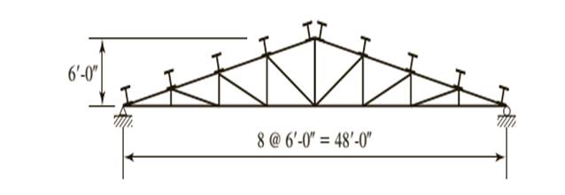
A truss with a roof system supporting a total gravity load of 40 psf of roof surface, half dead load and half snow. Spacing = 10 ft on centers.
Calculation:
Let’s calculate the nominal flexural strength about the X and Y axes.
Determine the strong axis bending strength. As neither the beam design charts nor the Z tables include shapes under W8 compute the flexural strength of W 6 X12. As there is no foot note to indicate otherwise the shape is compact.
We need to determine what controls the lateral torsional buckling.
Computing the values of
Substitute the values from the AISC Manual as
Substitute the values from the AISC Manual as
Now calculate the plastic moment for the section, we have
Where,
Substitute the values from the ASIC manual, we have
Let’s compare the values
Which implies that the strength is governed by inelastic Lateral- Torsional Buckling.
Compute the nominal strength of beam using the equation given as follows:
Substitute the values from the ASIC manual, we have
For the Y − axis, there is no flange buckling since the shape is compact.
Calculate the flexural strength about y- axis as:
Where,
Now, calculating the plastic moment of section about minor principal axis as:
Substitute the values, we have
Calculate the flexural strength about y axis, we have
Checking the upper limit using the following :
Substitute the values, we have
As the inequality is satisfied then the its OK.
Now using the LRFD method.
Following equation must be satisfied in order to know adhere to AISC specifications.
Where,
Now we need to find the values to substitute them
Where,
Where,
Where
As it is been given that half of load is dead load and half is snow load.
Therefore, as per the given conditions
Where,
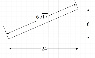
Following is the diagram from which we can find the value of angles.

Substitute the value for H = 6 ft and
Substitute the values
Substitute,
Find the flexural load about x-axis,
Similarly, for
Where,
Substitute,
Find the flexural load about x-axis,
Now, find the values of
As we have found every value, now we can substitute the values and check the adequacy
The equation is hence satisfied.
Conclusion:
Therefore, the beam is adequate.
(b)
The adequacy of W 6 X12 beam for use as purlin using ASD method.
Answer to Problem 5.5.16P
The beam is adequate to be used for purlin.
Explanation of Solution
Given:
A truss with a roof system supporting a total gravity load of 40 psf of roof surface, half dead load and half snow. Spacing = 10 ft on centers.

Calculation:
Now from Allowable stress design
Where
Now find the value of
Where,
Where,
Where
As it is been given that half of load is dead load and half is snow load.
Therefore, as per the given conditions
Calculate the load on the purlin as follows:
Following is the diagram from which we can find the value of angles.
Where,
Substitute the value for H = 6 ft and
Load on the purlin is as follows:
Substitute the values, we have
Now,
Where, L is the length of the beam and
Where,
Substitute the values, we have
Now find the value of
As we have found every value, now we can substitute the values and check the adequacy
Hence, the equation is satisfied.
Conclusion:
Therefore, the beam is adequate.
Want to see more full solutions like this?
Chapter 5 Solutions
Steel Design (Activate Learning with these NEW titles from Engineering!)

- Compute for the force in members FH, GH, and GI (USE METHOD OF SECTIONS) *For load P, take the last digit of your ID number example: ID # : 2187525, then P= 5 kN IF ZERO IS THE LAST DIGIT, TAKE THE 2ND TO THE LAST DIGIT example: ID #: 2187520, then P= 2 kNarrow_forwardA 3m both ends hinged timber column is made of Apitong wood with the following properties: Fc = 9.56 MPa (parallel to grain) Fc = 2.20 MPa (perpendicular to grain) E = 7310 MPaIf it has a square section with 200mm side dimension. Compute the actual slenderness ratio of the column. a. 12 b.13 c.14 d.15arrow_forward13.A rectangular beam has b = 300 mm and d = 410 mm. The beam is used to carry a factored moment of 20 kN-m. Assume f'c = 28 MPa and fy = 280 MPa. Calculate the required steel area in mm2. Express your answer in nearest whole numberarrow_forward
- The W8 * 48 cantilevered beam is made of A-36 steel and is subjected to the loading shown. Determine the displacement at its end A.arrow_forwardDetermine the design moment strengths of the section. fy = 60 ksi and f`c = 4 ksiarrow_forwardQuestion (1): A rectangular beam has a width b = 400 mm, and effective depth d = 850 mm and a total height h = 900 mm. The beam is subjected to an ultimate moment Mu = 1500 kN.m and an ultimate shear force Vu = 700 kN. 1- ) Design the beam for flexure to calculate the required area of steel. 2-) Using stirrups Φ 10 mm ( No.10) diameter, calculate the required spacing (s) between the stirrups at the ultimate shear force section. For all questions, Use f’c= 28 MPa and Fy= 420 MPaarrow_forward
- A built-upsection is to be used as a girder. It is simply supported over a span of 9 meters and laterally supported at supports and midspan. Use Fy=345MPa and Cb=1.0 Properties of the section: A=12,620mm2 d=450 mm tw=10 mm bf=300mm tf=14mm rx=203.88mm ry=70.67 mm Ix=524.59x106mm4 a.Determine the elastic section modulus, Sx. b.Determine the plastic section modulus, Zx. c.Determine the compactness of the section. d.Determine the lateral support condition. e.Determine the Allowable Flexural Strength of the girder. f.Determine the Ultimate Flexural Strength of the girder.arrow_forwardCheck the shear strength of an interior beam-column joint. The columns have 20 in. square cross-section, and 12ft clear height. The maximum probable moment strength of columns is (Mpr)ed. 520 ft-kips. The framing beams have the following geometry and reinforcement: Mpr = 345 ft-kips and Mpr = 213 ft-Kips; Top Bar = 5- #8 & Bot. Bar = 3 #8 Additional given data: fe= 4,000 psi; fy=60,000 psiarrow_forwarda)Enumerate all zero force member/s.b) Calculate the internal forces of all members in kN.c) Tabulate your propose W14 section for each member showing the internal load, available strengthand its corresponding DCR value.arrow_forward
- For the simple truss shown in the diagram, where the applied vertical downward load PP = 514 N, calculate the load in member AB (in N). Indicate a tensile load as +ve and a compressive load as -ve. Take aa = 2.7 metres.arrow_forwardThe 15m long cabble supports the load W1 and W2 as shown. Find the ratio W1/W2 for which the segment BC will be horizontal; that is B2 =oarrow_forward34 - A support is a fixed, B support is a sliding joint. loads M= 30 kNm, P1= 12 kN, P2= 13 kN, q1= 6 kN ⁄ m, q2= 7 kN ⁄ m , spans are a= 2 m, b= 3 m. The support reactions in the beam whose loading condition is given in the figure will be found. Accordingly, Ax = ?A) 22.25B) 0C) None.D) 39.25E) 21/2arrow_forward
 Steel Design (Activate Learning with these NEW ti...Civil EngineeringISBN:9781337094740Author:Segui, William T.Publisher:Cengage Learning