
Concept explainers
(a)
Maximum permissible load using LFRD method.
Answer to Problem 5.5.1P
The maximum permissible load from LFRD method is
Explanation of Solution
Given information:
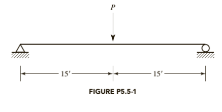
A W 10X 77 has continuous lateral support. The load P is a service live load and
Following is the given beam:

Calculation:
We have following properties for W 10X 77 from ASIC manual
| DesignationImperial (in x lb/ft) | Depth h (in) | Width w (in) | Web Thickness tw (in) | Flange Thickness tf (in) | Sectional Area (in2) | Weight (lbf/ft) | Static Parameters | ||||
| Moment of Inertia | Elastic Section Modulus | ||||||||||
| Ix (in4) | Iy (in4) | Sx (in3) | Sy (in3) | ||||||||
| W 10 x 77 | 10.60 | 10.190 | 0.530 | 0.870 | 22.6 | 77 | 455 | 154 | 85.9 | 30.1 | |
Let’s check for the compactness of the given W-shape beam using part
For Flange:
Where,
If the above condition satisfies, then the flange is non compact for flexure
Therefore, the web is compact.
Calculate the nominal flexural strength using the formula
Where,
Manual.
Now, calculate the maximum bending moment due to dead load, we have
Maximum bending moment for a simply supported beam carrying a dead UDL
Where,
Substitute,
Calculate the maximum bending moment for a simply supported beam carrying a concentrated
live load of the beam:
Where, P is the concentrated load and L is the length of the beam is.
Now, using Load Resistance and Factored design method:
Calculate the maximum permissible load P.
Substitute
Calculate P, by equating the maximum bending moment with the flexural strength of the beam;
Where,
Substitute
Conclusion:
Therefore, the maximum permissible load from LFRD method is
(b)
Maximum permissible load using ASD method.
Answer to Problem 5.5.1P
The maximum permissible load from ASD method is
Explanation of Solution
Given information:
A W 10X 77 has continuous lateral support. The load P is a service live load and
Calculation:
We have following properties for W 10X 77 from ASIC manual
| DesignationImperial (in x lb/ft) | Depthh (in) | Widthw (in) | Web Thicknesstw (in) | Flange Thicknesstf (in) | Sectional Area (in2) | Weight (lbf/ft) | Static Parameters | ||||
| Moment of Inertia | Elastic Section Modulus | ||||||||||
| Ix (in4) | Iy (in4) | Sx (in3) | Sy (in3) | ||||||||
| W 10 x 77 | 10.60 | 10.190 | 0.530 | 0.870 | 22.6 | 77 | 455 | 154 | 85.9 | 30.1 | |
Let’s check for the compactness of the given W-shape beam using part
For Flange:
Where,
If the above condition satisfies, then the flange is non compact for flexure
Therefore, the web is compact.
Calculate the nominal flexural strength using the formula
Now, calculate the maximum bending moment due to dead load, we have
Maximum bending moment for a simply supported beam carrying a dead UDL
Where,
Substitute,
Calculate the maximum bending moment for a simply supported beam carrying a concentrated
live load of the beam:
Where, P is the concentrated load and L is the length of the beam is.
Calculate the uniformly distributed load on the beam by equating
Allowable stress design method:
Substitute
Calculate P, by equating the maximum bending moment with the flexural strength of the beam:
Substitute,
Conclusion:
Therefore, the maximum permissible load from ASD method is
Want to see more full solutions like this?
Chapter 5 Solutions
Steel Design (Activate Learning with these NEW titles from Engineering!)


- The 400-kg uniform bar AB is shown in Figure is supported by a steel rod AC and a roller at B. If it supports a live distributed loading of 3 kN>m, determine the required diameter of the rod. The failure stress for the steel is sfail = 345 MPa. Use the LRFD method, where the resistance factor for tension is f = 0.9 and the load factors for the dead and live loads are gD = 1.2 and gL = 1.6, respectively.arrow_forwardCompute using Euler's formula: A square aluminum bar is to support a load of 65kN on a length of 4.50 m. Assume pinned ends, Determine the length of each side E = 70 GPa.arrow_forwardA simply supported beam 4 m long is carrying a variable load of w = 0 KN/m at the left support and w = 15 KN/m at the right. The beam has a width of 200 mm and a depth of 250 mm and is made up of 80% grade Narra. Use dressed dimension by reducing its dimensions by 10 mm. What is the actual bending stress of the beam in MPa? Blank 1 (use two decimal places, no need for unit)arrow_forward
- A rigid beam loaded with negligible mass is pinned at B and is supported by two indentical rods, except for the length. determine: a) The force in rod C b) The force in rod D *DRAW THE FBD; COMPLETE SOLUTION *USE 3 DEC PLACESarrow_forwardQuestion 1) F=22 kN single load, M=26 kN.m moment and w=17 kN/m distributed load are acting on the beam whose loading condition is given in the figure. The length L is also given as L=5 m. The cross-sectional properties of the beam are; body height yg=239 mm, body thickness xg=17 mm, flange width xf=185 mm, flange height yf=15 mm. Point E on the section is located just below the flange-body junction. It is desired to determine the stress state in the section taken from the C level of the beam. According to this; Question 1-D) Find the moment of inertia of the beam section. (Do your operations by converting the lengths to meters. Take at least 4 digits for the decimal part of your result and use the expression E for the decimal part. Write it as 5E-3 instead of 0.005.)arrow_forwardThe coefficient of kinetic friction under block A is 0.30 and under block B is 0.20. Find the acceleration of the system and the tension in each cord. include fbd and complete solution Expected answer a= 4.8 ft/s^2 T1=90.91 lb T2=255.36 lbarrow_forward
- A hollow steel [E = 30,000 ksi] tube (1) with an outside diameter of 3.50 in. and a wall thickness of 0.201 in. is fastened to a solid 2.00-in.-diameter aluminum [E = 10,000 ksi] rod. The assembly is attached to unyielding supports at the left and right ends and is loaded as shown. Assume P=19 kips, Q=13 kips, L1=7 ft, L2=9 ft, and L3=9 ft. Determine(a) the stresses in all parts of the axial structure.(b) the deflections of joints B and C.arrow_forwardA rectangular beam has an extended cantilever beam the is attached at the end of the beam. A force P = 165,000 N is acted at the end of cantilever beam. Take S1 = 230 mm, S2 = 300 mm. What is the angle of twist of the beam if the length of the beam is 1500 mm, G = 2.0 MPa. Show complete solution with FBDarrow_forwardDetermine the following if f'c=21 MPa and f(subscript)y= 415 MPa a.) balanced steel ratio b.) maximum steel ratio c.) nominal moment capacity in kn-m d.) ultimate moment capacityarrow_forward
- A hollow mild steel tube 5 m long, 4 cm internal diameter and 5 mm thick is used as a strut with both ends hinged. Find the crippling load and safe load taking FOS as 3. Taking E = 2 x 10⁵ N/mm2arrow_forwardA cantilever beam AB of length L = 6.5 ft supportsa trapezoidal distributed load of peak intensity q,and minimum intensity q/2, that includes the weight ofthe beam (see figure). The beam is a steel W12 X14wide-flange shape (see Table F-1(a), Appendix F).Calculate the maximum permissible load q basedupon (a) an allowable bending stress σallow =18 ksiand (b) an allowable shear stress τallow = 7.5 ksi.Note: Obtain the moment of inertia and section modulusof the beam from Table F-1(a).arrow_forwardA W12x79 of A573 Grade 60 (Fy = 415 MPa) steel is used as a compression member. It is 8 m long, pinned at the top fixed at bottom with additional lateral support at mid height in the weak direction. The properties are as follows: Ag = 14,500 sq.mm, Ix= 258.6 x10^6 mm ^4 Iy=84.375 x 10^6 mm^4. 57. Calculate the flexural buckling stress Fcr in MPaarrow_forward

 Structural Analysis (10th Edition)Civil EngineeringISBN:9780134610672Author:Russell C. HibbelerPublisher:PEARSON
 Principles of Foundation Engineering (MindTap Cou...Civil EngineeringISBN:9781337705028Author:Braja M. Das, Nagaratnam SivakuganPublisher:Cengage Learning
 Fundamentals of Structural AnalysisCivil EngineeringISBN:9780073398006Author:Kenneth M. Leet Emeritus, Chia-Ming Uang, Joel LanningPublisher:McGraw-Hill Education
 Traffic and Highway EngineeringCivil EngineeringISBN:9781305156241Author:Garber, Nicholas J.Publisher:Cengage Learning