
Mechanics of Materials (MindTap Course List)
9th Edition
ISBN: 9781337093347
Author: Barry J. Goodno, James M. Gere
Publisher: Cengage Learning
expand_more
expand_more
format_list_bulleted
Videos
Textbook Question
Chapter 5, Problem 5.6.12P
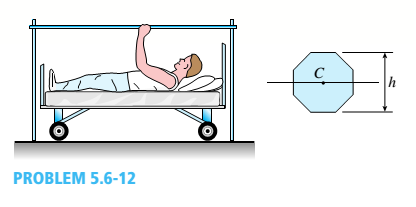
-12 A "trapeze bar" in a hospital room provides a means for patients to exercise while in bed (see figure). The bar is 2.1 m long and has a cross section in the shape of a regular octagon. The design load is 1.2 kN applied at the midpoint of the bar. and the allowable bending stress is 200 M Pa.
Determine the minimum height h of the bar. (Assume that the ends of the bar are simply supported and that the weight of the bar is negligible.)
Expert Solution & Answer

Trending nowThis is a popular solution!

Chapter 5 Solutions
Mechanics of Materials (MindTap Course List)
Ch. 5 - A steel wire with a diameter of d = 1/16 in. is...Ch. 5 - A copper wire having a diameter ofd = 4 mm is bent...Ch. 5 - A 4.75-in, outside diameter polyethylene pipe...Ch. 5 - A cantilever beam AB is loaded by a couple M0at...Ch. 5 - A thin strip of steel with a length of L =19 in....Ch. 5 - A bar of rectangular cross section is loaded and...Ch. 5 - A simply supported beam with a length L = 10 ft...Ch. 5 - A cantilever beam is subjected to a concentrated...Ch. 5 - A thin strip of hard copper (E = 16,000 ksi)...Ch. 5 - A steel wire (E = 200 GPa) of a diameter d = L25...
Ch. 5 - A thin, high-strength steel rule (E = 30 x 10ft...Ch. 5 - A simply supported wood beam AB with a span length...Ch. 5 - Beam ABC has simple supports at A and B and an...Ch. 5 - A simply supported beam is subjected to a in early...Ch. 5 - Each girder of the lift bridge (sec figure) is 180...Ch. 5 - A freight-car axle AS is loaded approximately as...Ch. 5 - A seesaw weighing 3 lb/ft of length is occupied by...Ch. 5 - During construction of a highway bridge, the main...Ch. 5 - The horizontal beam ABC of an oil-well pump has...Ch. 5 - A railroad tie (or sleeper) is subjected to two...Ch. 5 - A fiberglass pipe is lifted by a sling, as shown...Ch. 5 - A small dam of height h = 2.0 m is constructed of...Ch. 5 - Determine the maximum tensile stress (7, (due to...Ch. 5 - Determine the maximum bending stress emaxdue to...Ch. 5 - A simple beam A B of a span length L = 24 ft is...Ch. 5 - Determine the maximum tensile stress erand maximum...Ch. 5 - A cantilever beam A3, loaded by a uniform load and...Ch. 5 - A canti lever beam A B of a n isosceles t...Ch. 5 - A cantilever beam, a C12 x 30 section, is...Ch. 5 - A frame ABC travels horizontally with an...Ch. 5 - A beam ABC with an overhang from B to C supports a...Ch. 5 - A cantilever beam AB with a rectangular cross...Ch. 5 - A beam with a T-section is supported and loaded as...Ch. 5 - Consider the compound beam with segments AB and...Ch. 5 - A small dam of a height h = 6 ft is constructed of...Ch. 5 - A foot bridge on a hiking trail is constructed...Ch. 5 - A steel post (E=30×106) having thickness t = 1/8...Ch. 5 - Beam ABCDE has a moment release just right of...Ch. 5 - A simply supported wood beam having a span length...Ch. 5 - A simply supported beam (L = 4.5 m) must support...Ch. 5 - The cross section of a narrow-gage railway bridge...Ch. 5 - A fiberglass bracket A BCD with a solid circular...Ch. 5 - A cantilever beanie B is loaded by a uniform load...Ch. 5 - A simple beam of length L = 5 m carries a uniform...Ch. 5 - A simple beam AB is loaded as shown in the figure....Ch. 5 - A pontoon bridge (see figure) is constructed of...Ch. 5 - A floor system in a small building consists of...Ch. 5 - The wood joists supporting a plank Floor (see...Ch. 5 - A beam ABC with an overhang from B to C is...Ch. 5 - -12 A "trapeze bar" in a hospital room provides a...Ch. 5 - A two-axle carriage that is part of an over head...Ch. 5 - A cantilever beam AB with a circular cross section...Ch. 5 - A propped cantilever beam A BC (see figure) has a...Ch. 5 - A small balcony constructed of wood is supported...Ch. 5 - A beam having a cross section in the form of an un...Ch. 5 - A beam having a cross section in the form of a...Ch. 5 - Determine the ratios of the weights of four beams...Ch. 5 - Prob. 5.6.20PCh. 5 - A steel plate (called a cover ploie) having...Ch. 5 - A steel beam ABC is simply supported at A and...Ch. 5 - A retaining wall 6 ft high is constructed of...Ch. 5 - A retaining wall (Fig. a) is constructed using...Ch. 5 - A beam of square cross section (a = length of each...Ch. 5 - The cross section of a rectangular beam having a...Ch. 5 - A tapered cantilever beam A B of length L has...Ch. 5 - .2 A ligmio.irc ii supported by two vorlical beams...Ch. 5 - Prob. 5.7.3PCh. 5 - Prob. 5.7.4PCh. 5 - Prob. 5.7.5PCh. 5 - A cantilever beam AB with rectangular cross...Ch. 5 - A simple beam ABC having rectangular cross...Ch. 5 - A cantilever beam AB having rectangular cross...Ch. 5 - The shear stresses t in a rectangular beam arc...Ch. 5 - .2 Calculate the maximum shear stress tmaxand the...Ch. 5 - A simply supported wood beam is subjected to...Ch. 5 - A simply supported wood beam with overhang is...Ch. 5 - Two wood beams, each of rectangular cross section...Ch. 5 - A cantilever beam of length L = 2 m supports a...Ch. 5 - A steel beam of length L = 16 in. and...Ch. 5 - A beam of rectangular cross section (width/) and...Ch. 5 - A laminated wood beam on simple supports (figure...Ch. 5 - A laminated plastic beam of square cross section...Ch. 5 - A wood beam AB on simple supports with span length...Ch. 5 - A simply supported wood beam of rectangular cross...Ch. 5 - A square wood platform is 8 ft × 8 ft in area and...Ch. 5 - A wood beam ABC with simple supports at A and B...Ch. 5 - A wood pole with a solid circular cross section (d...Ch. 5 - A simple log bridge in a remote area consists of...Ch. 5 - A vertical pole consisting of a circular tube of...Ch. 5 - A circular pole is subjected to linearly varying...Ch. 5 - A sign for an automobile service station is...Ch. 5 - A steel pipe is subjected to a quadratic...Ch. 5 - -1 through 5.10-6 A wide-flange beam (see figure)...Ch. 5 - -1 through 5.10-6 A wide-flange beam (see figure)...Ch. 5 - -1 through 5.10-6 A wide-flange beam (see figure)...Ch. 5 - -1 through 5.10-6 A wide-flange beam (see figure)...Ch. 5 - -1 through 5.10-6 A wide-flange beam (see figure)...Ch. 5 - -1 through 5.10-6 A wide-flange beam (see figure)...Ch. 5 - A cantilever beam AB of length L = 6.5 ft supports...Ch. 5 - A bridge girder A B on a simple span of length L =...Ch. 5 - A simple beam with an overhang supports a uniform...Ch. 5 - A hollow steel box beam has the rectangular cross...Ch. 5 - A hollow aluminum box beam has the square cross...Ch. 5 - The T-beam shown in the figure has cross-sectional...Ch. 5 - Calculate the maximum shear stress tmax. in the...Ch. 5 - A prefabricated wood I-beam serving as a floor...Ch. 5 - A welded steel gird crhaving the erass section...Ch. 5 - A welded steel girder having the cross section...Ch. 5 - A wood box beam is constructed of two 260 mm × 50...Ch. 5 - A box beam is constructed of four wood boards as...Ch. 5 - Two wood box beams (beams A and B) have the same...Ch. 5 - A hollow wood beam with plywood webs has the...Ch. 5 - A beam of a T cross section is formed by nailing...Ch. 5 - The T-beam shown in the figure is fabricated by...Ch. 5 - A steel beam is built up from a W 410 × 85 wide...Ch. 5 - The three beams shown have approximately the same...Ch. 5 - Two W 310 × 74 Steel wide-flange beams are bolted...Ch. 5 - A pole is fixed at the base and is subjected to a...Ch. 5 - A solid circular pole is subjected to linearly...Ch. 5 - While drilling a hole with a brace and bit, you...Ch. 5 - An aluminum pole for a street light weighs 4600 N...Ch. 5 - A curved bar ABC having a circular axis (radius r...Ch. 5 - A rigid Trame ABC is formed by welding two steel...Ch. 5 - A palm tree weighing 1000 lb is inclined at an...Ch. 5 - A vertical pole of aluminum is fixed at the base...Ch. 5 - Because of foundation settlement, a circular tower...Ch. 5 - A steel bracket of solid circular cross section is...Ch. 5 - A cylindrical brick chimney of height H weighs w =...Ch. 5 - A flying but tress transmit s a load P = 25 kN,...Ch. 5 - A plain concrete wall (i.e., a wall with no steel...Ch. 5 - A circular post, a rectangular post, and a post of...Ch. 5 - Two cables, each carrying a tensile force P = 1200...Ch. 5 - Prob. 5.12.16PCh. 5 - A short column constructed of a W 12 × 35...Ch. 5 - A short column with a wide-flange shape is...Ch. 5 - A tension member constructed of an L inch angle...Ch. 5 - A short length of a C 200 × 17.1 channel is...Ch. 5 - The beams shown in the figure are subjected to...Ch. 5 - The beams shown in the figure are subjected to...Ch. 5 - A rectangular beam with semicircular notches, as...Ch. 5 - A rectangular beam with semicircular notches, as...Ch. 5 - A rectangular beam with notches and a hole (see...
Knowledge Booster


Learn more about
Need a deep-dive on the concept behind this application? Look no further. Learn more about this topic, mechanical-engineering and related others by exploring similar questions and additional content below.Similar questions
- Solve the preceding problem for a box beam with dimensions h = 0.5 m, h = 0.18 m, and t = 22 mm. The yield stress of the steel is 210 MPa.arrow_forwardA bimetallic beam used in a temperature-control switch consists of strips of aluminum and copper bonded together as shown in the figure, which is a cross-sectional view. The width of the beam is LO in,, and each strip has a thickness of 1/16 in. Under the action of a bending moment M = 12 lb-in, acting about the z axis, what are the maximum stresses aaand ecin the aluminum and copper, respectively? (Assume fA, = 10,5 x l0 psi and ecu= 16,8 × 10⁶ psi,)arrow_forwardA wood beam in a historic theater is reinforced with two angle sections at the outside lower corners (see figure). If the allowable stress in the wood is 12 M Pa and that in the steel is 140 M Pa, what is ratio of the maximum permissible moments for the beam before and after reinforcement with the angle sections? See Appendix F Table F-5(b) for angle section properties. Assume that ew= 12 GPa and E3=210 GPa.arrow_forward
- During construction of a highway bridge, the main girders are cantilevered outward from one pier toward the next (see figure). Each girder has a cantilever length of 48 m and an I-shaped cross section with dimensions shown in the figure. The load on each girder (during construction) is assumed to be 9,5 kN/m, which includes the weight of the girder. Determine the maximum bending stress in a girder due to this load.arrow_forwardA fiberglass bracket A BCD with a solid circular cross section has the shape and dimensions shown in the figure, A vertical load P = 40 N acts at the free end D. Determine the minimum permissible diameter ^nwi °f tnc bracket if the allowable bending stress in the material is 30 MPa and/? = 37 mm. Note: Disregard the weight of the bracket itself. If d = 10 nun, b = 37 mm, and= 30 MPa, what is the maximum value of load P if vertical load P at D is replaced with horizontal loads P at B and D (see figure part b)?arrow_forwardA W 200 x 41.7 wide-flange beam (see Table F-l(b), Appendix F) is simply supported with a span length of 2.5 m (see figure). The beam supports a concentrated load of 100 kN at 0.9 m from support B. At a cross section located 0,7 m from the left-hand support, determine the principal stresses tr, and 2and the maximum shear stress rnMJt at each of the following locations: (a) the top of the beam, (b) the top of the web, and (c) the neutral axis,arrow_forward
- A wood beam with a rectangular cross section (see figure) is simply supported on a span of length L. The longitudinal axis of the beam is horizontal, and the cross section is tilted at an angle a. The load on the beam is a vertical uniform load of intensity q acting through the centroid C. Determine the orientation of the neutral axis and calculate the maximum tensile stress bmaxif PROBLEMS 6.4-2 and 6.4-3 b = 80 mm, b = 140 mm, L = 1,75 m, a — 22.5°, and q = 7.5 kN/m.arrow_forwardA thin, high-strength steel rule (E = 30 x 10ft psi) having a thickness t = 0.175 in. and length L = 48 in. is bent by couples Mcinto a circular arc subtending a central angle a = 40° (sec figure), What is the maximum bending stress emax. in the rule? By what percent docs the stress increase or decrease if the central angle is increased by 10%? What percent increase or decrease in rule thickness will result in the maximum stress reaching the allowable value of 42 ksi?arrow_forwardThe composite beam shown in the figure is simply supported and carries a total uniform load of 40 kN/m on a span length of 4.0 m. The beam is built of a southern pine wood member having cross-sectional dimensions of 150 mm × 250 mm and two brass plates of cross-sectional dimensions 30 mm × 150 mm. Determine the maximum stresses (7b and ctwin the brass and wood, respectively, if the moduli of elasticity are EB= % GPa and Ew= 14 GPa. (Disregard the weight of the beam.) Find the required thickness of the brass plates so that the plate and wood reach their allowable stress values of Eb= 70 MPa and t Ew= 8.5 MPa simultaneously under the maximum moment. What is the maximum moment?arrow_forward
- A curved bar ABC having a circular axis (radius r = 12 in.) is loaded by forces P = 400 lb (see figure). The cross section of the bar is rectangular with height h and thickness t. If the allowable tensile stress in the bar is 12,000 psi and the height A = 1.25 in., what is the minimum required thickness rmax?arrow_forwardA weight W = 4500 lb falls from a height h onto a vertical wood pole having length L = 15 ft, diameter d = 12 in., and modulus of elasticity E = 1.6 × 10⁶ psi (see figure). If the allowable stress in the wood under an impact load is 2500 psi. what is the maximum permissible height h?arrow_forwardA canti lever beam A B of a n isosceles t rapezoi-dal cross section has a length L = 0.8 m, dimensions bx= 80 mm and b2= 90 mm, and height h = 110 mm (see figure). The beam is made of brass weighing 85 kN/m3. Determine the maximum tensile stress asand maximum compressive stressarrow_forward
arrow_back_ios
SEE MORE QUESTIONS
arrow_forward_ios
Recommended textbooks for you
 Mechanics of Materials (MindTap Course List)Mechanical EngineeringISBN:9781337093347Author:Barry J. Goodno, James M. GerePublisher:Cengage Learning
Mechanics of Materials (MindTap Course List)
Mechanical Engineering
ISBN:9781337093347
Author:Barry J. Goodno, James M. Gere
Publisher:Cengage Learning
Differences between Temporary Joining and Permanent Joining.; Author: Academic Gain Tutorials;https://www.youtube.com/watch?v=PTr8QZhgXyg;License: Standard Youtube License