
Videos
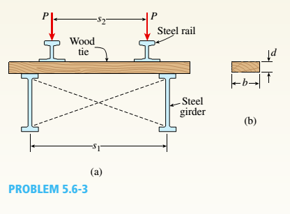
The cross section of a narrow-gage railway bridge is shown in part a of the figure. The bridge is constructed with longitudinal steel grinders that support the wood cross ties. The bridge is constructed with longitudinal steel girders that support the wood cross ties. The girders are restrained against lateral buckling by diagonal bracing, as indicated by the dashed lines.
The spacing of the girders is S1= 50 in. and the spacing of the rails is s2= 30 in. The load transmitted by each rail to a single tie is P = 1500 1b. The cross section of a tie, shown in part b of the figure, has a width b =5.0 in. and depth d.
Determine the minimum value of d based upon an allowable bending stress of 1125 psi in the wood tie. (Disregard the weight of the tie itself.)

Trending nowThis is a popular solution!

Chapter 5 Solutions
Mechanics of Materials (MindTap Course List)


- A U-shaped cross section of constant thickness is shown in the figure. Derive the following formula for the distance e from the center of the semicircle to the shear center. Also, plot a graph showing how the distance e (expressed as the non dimensional ratio e/r varies as a function of the ratio b/r. (Let b/r range from 0 to 2.)arrow_forwardAn L-shaped reinforced concrete slab 12 Ft X 12 ft, with a 6 Ft X 6 ft cut-out and thickness t = 9.0 in, is lifted by three cables attached at O, B, and D, as shown in the figure. The cables are are combined at point Q, which is 7.0 Ft above the top of the slab and directly above the center of mass at C. Each cable has an effective cross-sectional area of Ae= 0.12 in2. (a) Find the tensile force Tr(i = 1, 2, 3) in each cable due to the weight W of the concrete slab (ignore weight of cables). (b) Find the average stress ov in each cable. (See Table I-1 in Appendix I for the weight density of reinforced concrete.) (c) Add cable AQ so that OQA is one continuous cable, with each segment having Force T, which is connected to cables BQ and DQ at point Q. Repeat parts (a) and (b). Hini: There are now three Forced equilibrium equations and one constrain equation, T1= T4.arrow_forwardA long re Lai nine: wall is braced by wood shores set at an angle of 30° and supported by concrete thrust blocks, as shown in the first part of the figure. The shores are evenly spaced at 3 m apart. For analysis purposes, the wall and shores are idealized as shown in the second part of the figure. Note that the base of the wall and both ends of the shores are assumed to be pinned. The pressure of the soil against the wall is assumed to be triangularly distributed, and the resultant force acting on a 3-meter length of the walls is F = 190 kN. If each shore has a 150 mm X 150 mm square cross section, what is the compressive stressarrow_forward
- Cable DB supports canopy beam OABC as shown in the figure. Find the required cross-sectional area of cable BD if the allowable normal stress is 125 MPa. Determine the required diameter of the pins at 0, B, and D if the allowable stress in shear is 80 MPa. Assume that canopy beam weight is w = 8 kN. note The pins at 0, A, D and D are in double shear. Consider only the weight of the canopy; disregard the weight of cable DB.arrow_forwardTwo pipe columns (AB, FC) are pin-connected to a rigid beam (BCD), as shown in the figure. Each pipe column has a modulus of E, but heights (L1or L2) and outer diameters (d1or different for each column. Assume the inner diameter of each column is 3/4 of outer diameter. Uniformly distributed downward load q = 2PIL is applied over a distance of 3L/4 along BC, and concentrated load PIA is applied downward at D. (a) Derive a formula for the displacementarrow_forwardDetermine the shape factor f for a cross section in the shape of a double trapezoid having the dimensions shown in the figure. Also, check your result for the special cases of a rhombus (b1= 0) and a rectangle (b1= b2).arrow_forward
- A large precast concrete panel for a warehouse is raised using two sets of cables at two lift lines, as shown in the figure part a. Cable 1 has a length L1 = 22 Ft, cable 2 has a length L2= 10 ft, and the distance along the panel between lift points Band D is d = 14 ft (see figure part b). The total weight of the panel is W = 85 kips. Assuming the cable lift Forces F at each lift line are about equal, use the simplified model of one half of the panel in figure part b to perform your analysis for the lift position shown. Find the required cross-sectional area AC of the cable if its breaking stress is 91 ksi and a factor of safety of 4 with respect to failure is desired.arrow_forwardA sign for an automobile service station is supported by two aluminum poles of hollow circular cross section, as shown in the figure. The poles are being designed to resist a wind pressure of 75 lb/ft" against the full area of the sign. The dimensions of the poles and sign are hx= 20 ft, /r =5 ft, and h = 10 ft. To prevent buckling of the walls of the poles, the thickness e is specified as one-tenth the outside diameter d. (a) Determine the minimum required diameter of the poles based upon an allowable bending stress of 7500 psi in the aluminum. (b) Determine the minimum required diameter based upon an allowable shear stress of 300 psi.arrow_forwardThe composite beam shown in the figure is simply supported and carries a total uniform load of 40 kN/m on a span length of 4.0 m. The beam is built of a southern pine wood member having cross-sectional dimensions of 150 mm × 250 mm and two brass plates of cross-sectional dimensions 30 mm × 150 mm. Determine the maximum stresses (7b and ctwin the brass and wood, respectively, if the moduli of elasticity are EB= % GPa and Ew= 14 GPa. (Disregard the weight of the beam.) Find the required thickness of the brass plates so that the plate and wood reach their allowable stress values of Eb= 70 MPa and t Ew= 8.5 MPa simultaneously under the maximum moment. What is the maximum moment?arrow_forward
- A tie-down on the deck of a sailboat consists of a bent bar boiled at both ends, as shown in the figure. The diameter dBof the bar is 1/4 in., the diameter D Wof the washers is 7/8 in., and the thickness is of the fiberglass deck is 3/8 in. If the allowable shear stress in the fiberglass is 300 psi, and the allowable bearing pressure between the washer and the fiberglass is 550 psi, what is the allowable load P allowon the tie-down?arrow_forwardQuestion 1) F=35 kN single load, M=45 kN.m moment and w=16 kN/m distributed load are acting on the beam whose loading condition is given in the figure. The length L is also given as L=4 m. The cross-sectional properties of the beam are; body height yg=225 mm, body thickness xg=14 mm, flange width xf=194 mm, flange height yf=11 mm. Point P on the section is located just above the flange-body junction. It is desired to determine the stress state at the P point in the section taken from the B line of the beam. According to this;Question 1-D) For a section taken from the B line of the beam; Find the normal stress at point P on the beam section due to the bending moment MB. (Write your result in MPa.)Question1-E) For a section taken from the B line of the beam; Find the shear stress at point P on the beam section due to the shear force VB. (Write your result in MPa.)arrow_forwardQuestion 1) F=35 kN single load, M=45 kN.m moment and w=16 kN/m distributed load are acting on the beam whose loading condition is given in the figure. The length L is also given as L=4 m. The cross-sectional properties of the beam are; body height yg=225 mm, body thickness xg=14 mm, flange width xf=194 mm, flange height yf=11 mm. Point P on the section is located just above the flange-body junction. It is desired to determine the stress state at the P point in the section taken from the B line of the beam. According to this;Question1-A) Find the shear force (VB) at point B. (Write your result in kN.)Question1-B) Find the bending moment (MB) at point B. (Write your result in kN.m.)Question 1-C) Find the moment of inertia of the beam section. (Do your operations by converting the lengths to meters. Take at least 4 digits for the decimal part of your result and use the expression E for the decimal part. Write it as 5E-3 instead of 0.005.)arrow_forward
 Mechanics of Materials (MindTap Course List)Mechanical EngineeringISBN:9781337093347Author:Barry J. Goodno, James M. GerePublisher:Cengage Learning