
Concept explainers
Videos
a.
The bending stress
a.
Answer to Problem 5.7.4P
The bending stress
Explanation of Solution
Given:
Calculate the maximum bending stress.
For maximum condition, we take:
Now, plotting the graph for
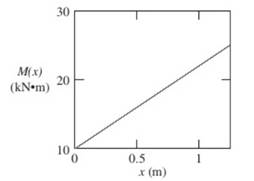
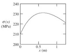
Now, the maximum bending stress is calculated.
The largest bending stress is calculated as:
Conclusion:
Therefore, the bending stress
b.
The bending stress
b.
Answer to Problem 5.7.4P
The bending stress
Explanation of Solution
The largest bending stress is calculated as:
Conclusion:
Therefore, the bending stress
c.
The distance of maximum bending stress
c.
Answer to Problem 5.7.4P
The distance of maximum bending stress
Explanation of Solution
The distance of maximum bending stress
Conclusion:
Therefore, the distance of maximum bending stress
d.
The magnitude of maximum bending stress
d.
Answer to Problem 5.7.4P
The magnitude of maximum bending stress
Explanation of Solution
The magnitude of maximum bending stress
Conclusion:
Therefore, the magnitude of maximum bending stress
e.
The magnitude of maximum bending stress.
e.
Answer to Problem 5.7.4P
The magnitude of maximum bending stress is 214 MPa.
Explanation of Solution
Given:
Calculate the maximum bending stress.
For maximum condition, we take:
Now, plotting the graph for
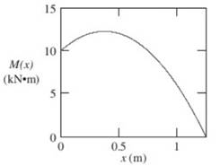
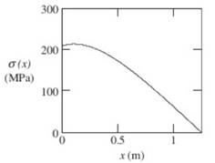
Now, the maximum bending stress is calculated.
The largest bending stress is calculated as:
The largest bending stress is calculated as:
Conclusion:
Therefore, the magnitude of maximum bending stress is 214 MPa.
Want to see more full solutions like this?
Chapter 5 Solutions
Mechanics of Materials (MindTap Course List)


- A reinforced concrete slab (see figure) is reinforced with 13-mm bars spaced 160 mm apart at d = 105 mm from the top of the slab. The modulus of elasticity for the concrete is Ec= 25 GPa, while that of the steel is £s = 200 G Pa. Assume that allowable stresses for concrete and steel arecrac = 9.2 MPa and us = 135 MPa. l()5 mm Find the maximum permissible positive bending moment for a l-m wide strip of the slab. What is the required area of steel reinforcement, A^ if a balanced condition must be achieved? What is the allowable positive bending moment? (Recall that in a balanced design, both steel and concrete reach allowable stress values simultaneously under the design moment.)arrow_forwardA beam ABCD with a vertical arm CE is supported as a simple beam al A and D (see figure part a). A cable passes over a small pulley that is attached to the arm at E. One end of the cable is attached to the beam at point B. (a) What is the force P in the cable if the bending moment in the beam just lo the left of point C is equal numerically to 640 lb-ft? Note: Disregard the widths of the beam and vertical arm and use centerline dimensions when making calculations. (b) Repeat part (a) if a roller support is added at C and a shear release is inserted just left of C (see figure part b).arrow_forwardA wood beam 8 in. wide and 12 in. deep (nominal dimensions) is reinforced on top and bottom by 0,25-in.-thick steel plates (see figure part a), (a) Find the allowable bending moment A/max about the z axis if the allowable stress in the wood is 1100 psi and in the steel is 15,000 psi, (Assume that the ratio of the moduli of elasticity of steel and wood is 20.) (b) Compare the moment capacity of the beam in part a with that shown in the figure part b which has two 4 in. × 12 in, joists (nominal dimensions) attached to a 1/4 in, × 11.0 in, steel plate.arrow_forward
- A reinforced concrete T-beam (see figure) is acted on by a positive bending moment of M = 175 kip-ft. Steel reinforcement consists of four bars of 1.41-inch diameter. The modulus of elasticity for the concrete is Ec= 3000 ksi while that of the steel is £s = 29,000 ksi. Let b = 48 im, rf = 4 in., bw=15 in,, and d = 24 in, Find the maximum stresses in steel and concrete, If allowable stresses for concrete and steel are o"ac = 1400 psi and tr^ =18 ksi, respectively, what is the maximum permissible positive bending moment?arrow_forwardA reinforced concrete beam (see figure) is acted on by a positive bending moment of M = 160 kN · m. Steel reinforcement consists of 4 bars of 28 mm diameter. The modulus of elasticity for the concrete is Ec= 25 GPa while that of the steel is Es= 200 GPa. Find the maximum stresses in steel and concrete. If allowable stresses for concrete and steel are T2= 9.2 MPa and t1= 135 MPa, respectively, what is the maximum permissible positive bending moment? What is the required area of steel reinforcement, A$ if a balanced condition must be achieved? What is the allowable positive bending moment? (Recall that in a balanced design, both steel and concrete reach allowable stress values simultaneously under the design moment.)arrow_forwardA r o lukI f/frm f «m t ub e of ou t sid e d ia met er ^ and a copper core of diameter dxare bonded to form a composite beam, as shown in the figure, (a) Derive formulas for the allowable bending moment M that can be carried by the beam based upon an allowable stress <7Ti in the titanium and an allowable stress (u in the copper (Assume that the moduli of elasticity for the titanium and copper are Er- and £Cu, respectively.) (b) If d1= 40 mm, d{= 36 mm, ETl= 120 GPa, ECu= 110 GPa, o-Ti = 840 MPa, and ctqj = 700 MPa, what is the maximum bending moment Ml (c) What new value of copper diameter dtwill result in a balanced design? (i.e., a balanced design is that in which titanium and copper reach allow- able stress values at the same time).arrow_forward
- Find support reactions at A and D and then calculate the axial force N. shear force 1 and bending moment 11 at mid-span of column BD. Let L = 4 m, q0 = 160N/m, P = 200N, and M0= 380 N .m.arrow_forwardA foot bridge on a hiking trail is constructed using two timber logs each having a diameter d = 0.5 m (see figure a). The bridge is simply supported and has a length L = 4 m. The top of each log is trimmed to form the walking surface (see Fig, b)LA simplified model of the bridge is shown in Fig. g. Each log must carry its own weight w = 1.2 kN/m and the weight (P = 850 N) of a person at mid-span, (see Fig. b). Determine the maximum tensile and compressive stresses in the beam (Fig, b) due to bending. If load h is unchanged, find the maximum permissible value of load ... if the allowable normal stress in tension and compression is 2.5 M Pa.arrow_forwardA vertical pole of solid, circular cross section is twisted by horizontal forces P = 5kN acting at the ends of a rigid horizontal arm AB (see figure part a). The distance from the outside of the pole to the line of action of each force is c = 125 mm (sec figure part b) and the pole height L = 350 mm. (a) If the allowable shear stress in the pole is 30 MPa, what is the minimum required diameter dminof the pole? (b) What is the torsional stiffness of the pole (kN · m/rad)? Assume that G = 28 GPa. (c) If two translation al springs, each with stiffness k =2550 kN/m, are added at 2c/5 from A and B (see figure part c), repeat part (a) to find dmin. Hint: Consider the pole and pair of springs as "springs in parallel."arrow_forward
- Find expressions for shear force V and moment M at mid-span of beam AB in terms of peak load intensity q0and beam length variables a and L Let a = 5L/b.arrow_forwardSolve the preceding problem using a W 310 x 129 section, L = 1.8 m, P = 9.5 kN, and or x= 60°. See Table F-l(b) of Appendix F For the dimensions and properties of the beam.arrow_forwardA steel beam ABC is simply supported at A and fiand has an overhang BC of length L = 150 mm (see figure). The beam supports a uniform load of intensity q = 4,0 kN/m over its entire span AB and l.5g over BC. The cross section of the beam is rectangular with width h and height 2b. The allowable bending stress in the steel iso"a|]ûW = 60 MPa, and its weight density is y = 77.0 kN/m . Disregarding the weight of the beam, calculate the required width b of the rectangular cross section. Taking into account the weight of the beam, calculate the required width b.arrow_forward
 Mechanics of Materials (MindTap Course List)Mechanical EngineeringISBN:9781337093347Author:Barry J. Goodno, James M. GerePublisher:Cengage Learning