
The time
Answer to Problem 5.79HP
The value of
Explanation of Solution
Calculation:
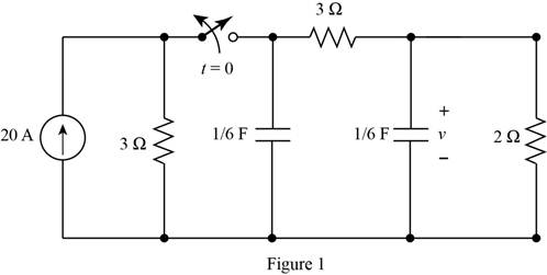
The given circuit is shown in Figure 1
For time
The required diagram is shown in Figure 2
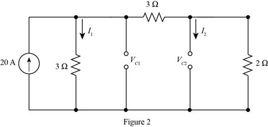
The value for the current through the resistance of
The value for the current through the resistance of
The expression for the initial voltage across the capacitor
Substitute
The expression for the initial voltage across the capacitor
Substitute
For time
The required diagram is shown in Figure 3
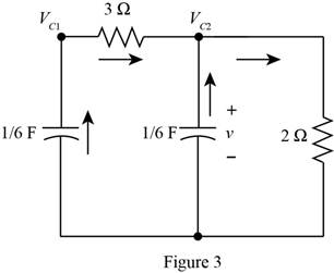
Apply KCL to the node
Substitute
Apply KCL to the node
Substitute
Substitute
The standard second order equation for the above equation is given by,
From above and from equation (2), the natural frequency of the circuit is calculated as,
The damping ratio of the circuit is calculated as,
Substitute
The general equation for the voltage across the capacitor is given by,
Substitute
Substitute
Substitute
Substitute
Apply KCL to the node
Substitute
Substitute
The differentiation of equation (3) with respect to
Substitute
Substitute
Substitute
Substitute
Substitute
Substitute
Substitute
Thus, the value of
Conclusion:
Therefore, the value of
Want to see more full solutions like this?
Chapter 5 Solutions
Principles and Applications of Electrical Engineering

- Suppose we have a capacitance C discharging through a resistance R. Define and give an expression for the time constant. To attain a long time constant, do we need large or small values for R? For C?arrow_forward5)This MCQ QUESTION FROM BASIC POWER ELECTRICAL ENGINEERING course.arrow_forwardA point charge of5nCis located at the origin. IfV = 2Vat(0,6,−8),find the potential atA(−3,2,6)andB(1,5,7).arrow_forward
- Discuss the advantages and challenges of modeling non-linear systems and the methods used to handle non-linearity in system models.arrow_forwardDetermine the initial and final conditions for thecircuit of Figure P5.29.arrow_forwardDraw the Thévenin and Norton equivalent circuits for Figure P5.91, labeling the elements and terminals.arrow_forward
- Determine the power for each source shown in Figure P5.76. Also, state whether each source is delivering or absorbing energy.arrow_forwardConsider more realistic situation, silicons intrinsic Fermi level isn't at the midgap. Please find the energy differences between real Fermi level and midgap Please give some explanations.arrow_forwardA solid specimen of dielectric dielectric constant of 4.0, shown in the figure has an internal void of thickness 1mm. The specimen is 1cm thick and is subjected to a voltage of 80 kV(rms). If the void is filled with air and if the breakdown strength of air can be taken as 30 kV(peak)/cm, find the voltage at which an internal dischargearrow_forward
- Could you please go more in depth about how to create the ac equivalant model? thank youarrow_forwardThe equation of the charge on the capacitor at any time t for an LRC series circuits is givenas a) Assume there is no initial charge and current, sketch the graph of the charge. b) What happen to the charge after a long time? c) State the transient and the steady state terms.arrow_forwardAssume that S1 and S2 close at t = 0 in FigureP5.41.a. Find the capacitor voltage vC(t) at t = 0+. b. Find the time constant τ for t ≥ 0.c. Find an expression for vC(t), and sketch thefunction.d. Find vC(t) for each of the following values of t:0, τ, 2τ, 5τ, 10τ .arrow_forward
 Introductory Circuit Analysis (13th Edition)Electrical EngineeringISBN:9780133923605Author:Robert L. BoylestadPublisher:PEARSON
 Delmar's Standard Textbook Of ElectricityElectrical EngineeringISBN:9781337900348Author:Stephen L. HermanPublisher:Cengage Learning
 Programmable Logic ControllersElectrical EngineeringISBN:9780073373843Author:Frank D. PetruzellaPublisher:McGraw-Hill Education
 Fundamentals of Electric CircuitsElectrical EngineeringISBN:9780078028229Author:Charles K Alexander, Matthew SadikuPublisher:McGraw-Hill Education
 Electric Circuits. (11th Edition)Electrical EngineeringISBN:9780134746968Author:James W. Nilsson, Susan RiedelPublisher:PEARSON
 Engineering ElectromagneticsElectrical EngineeringISBN:9780078028151Author:Hayt, William H. (william Hart), Jr, BUCK, John A.Publisher:Mcgraw-hill Education,