
Concept explainers
Videos
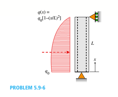
A steel pipe is subjected to a quadratic distributed load over its height with the peak intensity q0at the base (see figure). Assume the following pipe properties and dimensions: height L, outside diameter d = 200 mm, and wall thickness f = 10 mm. Allowable stresses for flexure and shear are o~a=125 MPa and Ta= 30 MPa,
- If L = 2.6 m, Fmd^0ayM (kN/m), assuming that allowable flexure and shear stresses in the pipe are not to be exceeded.
- If q0= 60 kN/m, find the maximum height Lraajl(m) of the pipe if the allowable flexure and shear stresses in the pipe arc not to be exceeded.
(a)
The maximum uniform load intensity
Answer to Problem 5.9.6P
The maximum load intensity
Explanation of Solution
Given information:
The allowable stress is
Write the expression intensity.
Here, the intensity is
Write the expression for the differential Equation.
Here, the modulus of elasticity is
Integrate the Equation (II) with respect to x.
Applying, the boundary condition at point
Here, the reaction force at
Substitute
Applying, the boundary condition at point
Here, the reaction force at the point
Integrate the Equation (V) with respect to x.
Substitute
Here, the bending moment is
Applying the boundary condition at fixed end
Applying the boundary condition at proper end
Substitute
Substitute
Differentiate the Equation (X) with respect to x
Write the expression of the flexible stress.
Here, the allowable stress is
Write the expression of the allowed shear stress.
Here, the shear stress is
Write the expression for the area.
Calculation:
Substitute
Substitute
Substitute
Substitute
Substitute
Conclusion:
The maximum load intensity
(b)
The maximum height of the pipe.
Answer to Problem 5.9.6P
The maximum height of the pipe is
Explanation of Solution
Write the expression of the bending moment in terms of length.
Calculation:
Substitute
Conclusion:
The maximum height of the pipe is
Want to see more full solutions like this?
Chapter 5 Solutions
Mechanics of Materials (MindTap Course List)


- A thin-walled circular tube and a solid circular bar of the same material (see figure) are subjected to torsion. The tube and bar have the same cross-sectional area and the same length. What is the ratio of the strain energy U1in the tube to the strain energy U2in the solid bar if the maximum shear stresses are the same in both cases? (For the tube, use the approximate theory for thin-walled bars.)arrow_forwardA thin-walled steel tube of rectangular cross section (see figure) has centerline dimensions b = 150 mm and h = 100 mm. The wall thickness t is constant and equal to 6.0 mm. Determine the shear stress in the tube due to a torque T = 1650 N · m. Determine the angle of twist (in degrees) if the length L of the tube is 1.2 m and the shear modulus G is 75 GPa.arrow_forwardA cantilever beam(Z, = 6 ft) with a rectangular cross section (/> = 3.5 in., h = 12 in.) supports an upward load P = 35 kips at its free end. (a) Find the state of stress ((7T, o^., and r in ksi) on a plane-stress element at L/2 that is i/ = 8 in. up from the bottom of the beam. Find the principal normal stresses and maximum shear stress. Show these stresses on sketches of properly oriented elements. (b) Repeat part (a) if an axial compressive centroidal load N = 40 kips is added at Barrow_forward
- A cylindrical pressure vessel having a radius r = 14 in. and wall thickness t = 0,5 in, is subjected to internal pressure p = 375 psi, In addition, a torque T = 90 kip-ft acts at each end of the cylinder (see figure), (a) Determine the maximum tensile stress ctniXand the maximum in-plane shear stress Tmjv in the wall of the cylinder. (b) If the allowable in-plane shear stress is 4.5 ksi, what is the maximum allowable torque T\ (c) If 7 = 150 kip-ft and allowable in-plane shear and allowable normal stresses are 4.5 ksi and 11.5 ksi, respectively, what is the minimum required wall thicknessarrow_forwardA hollow circular tube having an inside diameter of 10.0 in, and a wall thickness of 1.0 in. (see figure) is subjected to a torque T = 1200 kip-in. Determine the maximum shear stress in the tube using (a) the approximate theory of thin-walled tubes, and (b) the exact torsion theory. Does the approximate theory give conservate or nonconservative results?arrow_forward-3 An element of aluminum in the form of a rectangular parallelepiped (see figure) of dimensions a = 5.5 in., h = 4.5 in, and c = 3.5 in. is subjected to iriaxial stresses = 12,500 psi, o. = —5000 psi, and ci. = —1400 psi acting on the x,i, and z faces, respectively. Determine the following quantities: (a) the maxim um shear stress in the material; (b) the changes ..la, .11. and 1c in the dimensions of the element: (C) the change .IJ’ in the volume: (d) the strain energy U stored in the element: (e) the maximum value of cr1 when the change in volume must be limited to 0.021%; and (f) the required value of o when the strain energy must be 900 in.-lb. (Assume E = 10,400 ksi and v = 0.33.)arrow_forward
- A pressurized cylindrical tank with flat ends is loaded by torques T and tensile forces P (sec figure), The tank has a radius of r = 125 mm and wall thickness t = 6.5 mm. The internal pressure p = 7.25 MPa and the torque T = 850 N m. (a) What is the maximum permissible value of the forces P if the allowable tensile stress in the wall of the cylinder is 160 MPa? (b) If forces P = 400 kN, what is the maximum acceptable internal pressure in the tank?arrow_forwardA reinforced concrete slab (see figure) is reinforced with 13-mm bars spaced 160 mm apart at d = 105 mm from the top of the slab. The modulus of elasticity for the concrete is Ec= 25 GPa, while that of the steel is £s = 200 G Pa. Assume that allowable stresses for concrete and steel arecrac = 9.2 MPa and us = 135 MPa. l()5 mm Find the maximum permissible positive bending moment for a l-m wide strip of the slab. What is the required area of steel reinforcement, A^ if a balanced condition must be achieved? What is the allowable positive bending moment? (Recall that in a balanced design, both steel and concrete reach allowable stress values simultaneously under the design moment.)arrow_forward: A hollow, pressurized sphere having a radius r = 4.8 in, and wall thickness t = 0.4 in. is lowered into a lake (see figure). The compressed air in the tank is at a pressure of 24 psi (gage pressure when the tank: is out of the water). At what depth D0will the wall of the tank be subjected to a compressive stress of 90 psi?arrow_forward
- Consider the preceding problem if the beam has width h = 15 mm, the aluminum strips have thickness t = 3 mm, the plastic segments have heights d = 40 mm and 3 tf = 120 mm, and the total height of the beam is h = 212 mm. Also, the moduli of elasticity are EA= 75 GPa and Ep=3 GPa, respectively. Determine the maximum stresses o., and o\, in the aluminum and plastic, respectively, due to a bending moment of 1.0 kN - m.arrow_forward-21 Plastic bar AB of rectangular cross section (6 = 0.75 in. and h = 1.5 in.) and length L = 2 Ft is Fixed at A and has a spring support (Ar = 18 kips/in.) at C (see figure). Initially, the bar and spring have no stress. When the temperature of the bar is raised hy foot. the compressive stress on an inclined plane pq at Lq = 1.5 Ft becomes 950 psi. Assume the spring is massless and is unaffected by the temperature change. Let a = 55 × l0-6p and E = 400 ksi. (a) What is the shear stresst9 on plane pq? What is angle 07 =1 Draw a stress element oriented to plane pq, and show the stresses acting on all laces of this element. (c) If the allowable normal stress is ± 1000 psi and the allowable shear stress is ±560 psi, what is the maximum permissible value of spring constant k if the allowable stress values in the bar are not to be exceeded? (d) What is the maximum permissible length L of the bar if the allowable stress values in the bar are not be exceeded? (Assume £ = IB kips/in.) (e) What is the maximum permissible temperature increase (A7") in the bar if the allowable stress values in the bar are not to be exceeded? (Assume L = 2 ft and k = L& kips/inarrow_forwardA reinforced concrete T-beam (see figure) is acted on by a positive bending moment of M = 175 kip-ft. Steel reinforcement consists of four bars of 1.41-inch diameter. The modulus of elasticity for the concrete is Ec= 3000 ksi while that of the steel is £s = 29,000 ksi. Let b = 48 im, rf = 4 in., bw=15 in,, and d = 24 in, Find the maximum stresses in steel and concrete, If allowable stresses for concrete and steel are o"ac = 1400 psi and tr^ =18 ksi, respectively, what is the maximum permissible positive bending moment?arrow_forward
 Mechanics of Materials (MindTap Course List)Mechanical EngineeringISBN:9781337093347Author:Barry J. Goodno, James M. GerePublisher:Cengage Learning