
Concept explainers
Videos
(a)
Find the two-component Thevenin equivalent of the network
(a)
Answer to Problem 63E
The Thevenin equivalent resistance is
Explanation of Solution
Formula used:
The expression for the equivalent resistor when resistors are connected in series is as follows:
Here,
The expression for the equivalent resistor when resistors are connected in parallel is as follows:
Here,
The
 o
o
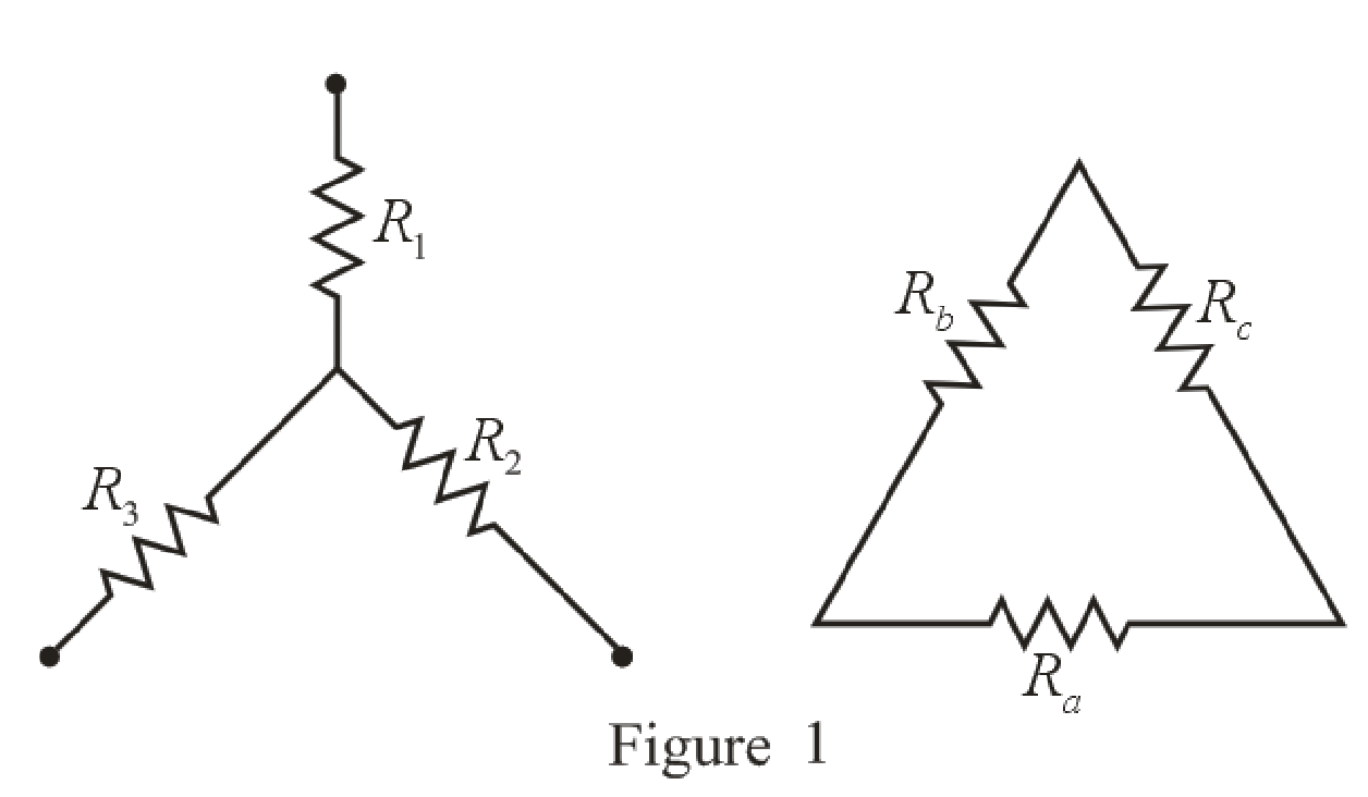
Refer to the redrawn Figure 1:
The expression for the conversion of
Here,
Calculation:
To find equivalent resistance of a circuit the independent voltage source is replaced by short circuit
The redrawn circuit diagram is given in Figure 2:
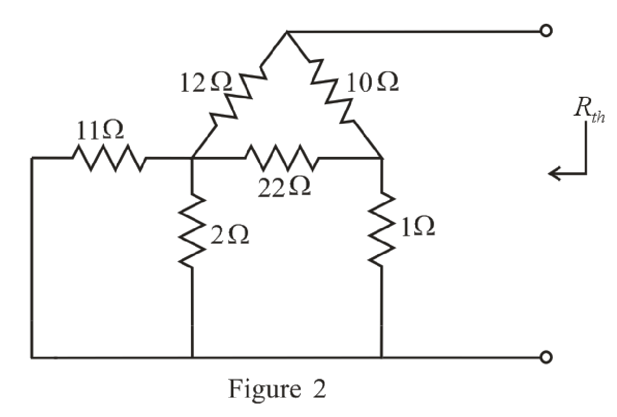
Refer to the redrawn Figure 2:
Substitute
Rearrange the equation for
The simplified circuit diagram is given in Figure 3:
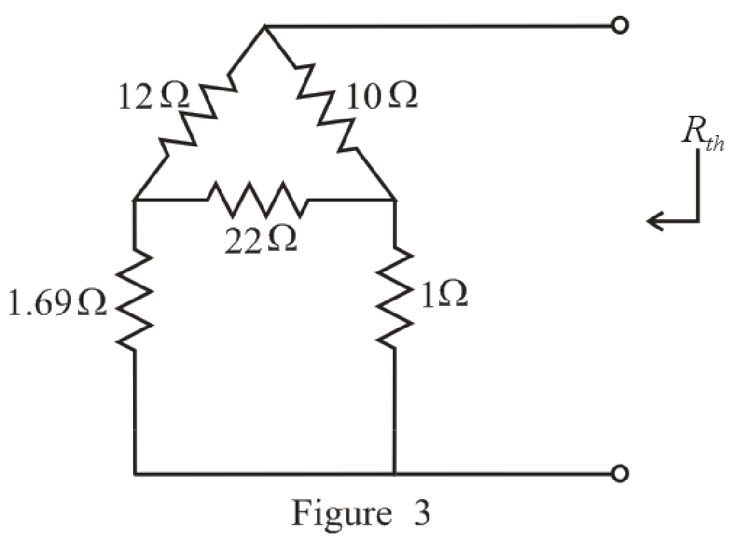
Refer to the redrawn Figure 3:
Substitute
Substitute
Substitute
The simplified circuit diagram is given in Figure 4.
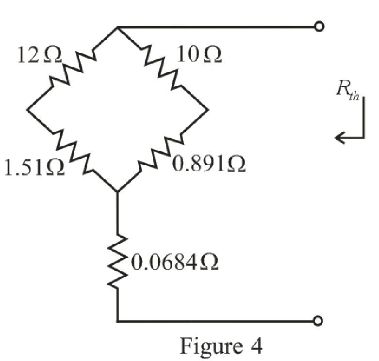
Refer to the redrawn Figure 4:
Substitute
Substitute
Substitute
Rearrange the equation for
The simplified circuit diagram is given in Figure 5.
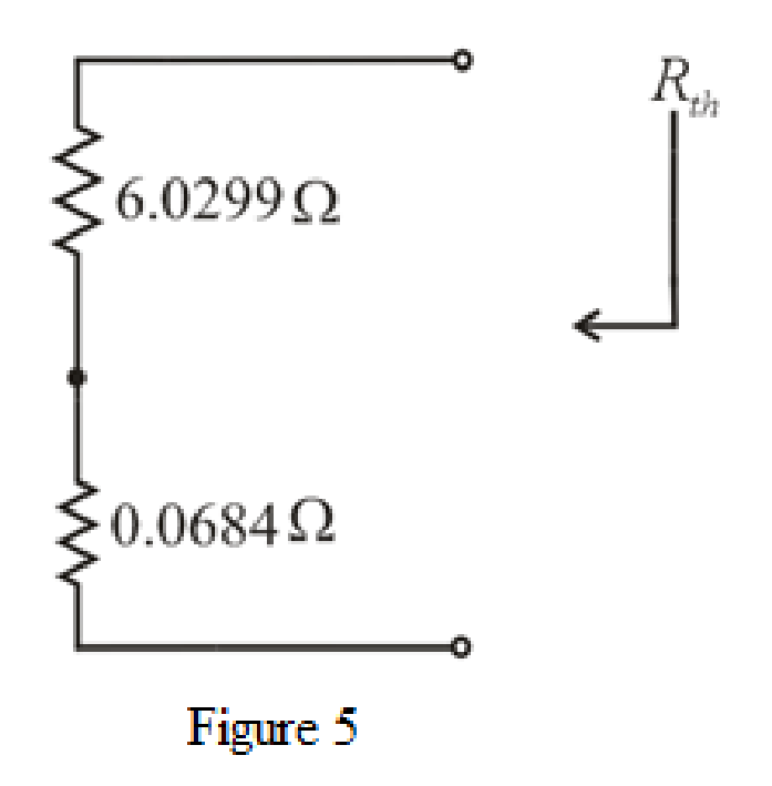
Refer to the redrawn Figure 5:
Substitute
The simplified circuit diagram is given in Figure 6.
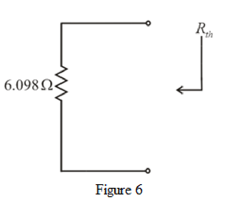
Refer to the redrawn Figure 6:
So, the Thevenin equivalent resistance is
The redrawn circuit diagram is given in Figure 7.
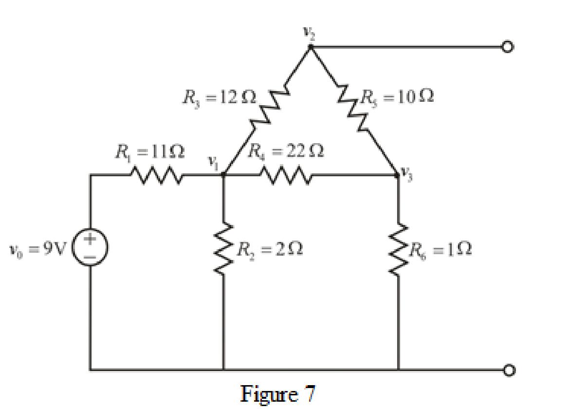
Refer to the redrawn Figure 7:
Apply KCL at node 1:
Here,
Substitute
Rearrange for
Apply KCL at node 2:
Here,
Substitute
Rearrange for
Apply KCL at node 3:
Here,
Substitute
Rearrange for
The equations (7), (9) and (11) can be written in matrix form as:
Therefore, by Cramer’s rule,
The determinant of the coefficient matrix is as follows:
The 1st determinant is as follows:
The 2nd determinant is as follows:
The 3rd determinant is as follows:
Simplify for
Simplify for
Simplify for
So, the Thevenin voltage
Conclusion:
Thus, the Thevenin equivalent resistance is
(b)
Find the power dissipated by a
(b)
Answer to Problem 63E
Thepower dissipated by a
Explanation of Solution
Given Data:
The load resistance is
Formula used:
The expression for the power dissipated by a resistor is as follows:
Here,
Calculation:
The redrawn circuit diagram is given in Figure 8.
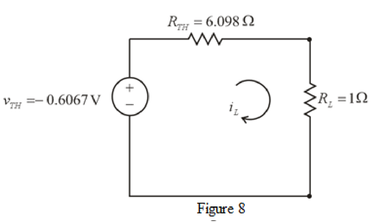
Refer to the redrawn Figure 8:
The expression for the current flowing in the circuit is as follows:
Here,
Substitute
Substitute
Conclusion:
Thus, the power dissipated by a
Want to see more full solutions like this?
Chapter 5 Solutions
Loose Leaf for Engineering Circuit Analysis Format: Loose-leaf


- EX:- re drow the network of fig. 5.183 for the AC respon with the re model inserted between the appropriate terminals include ro.arrow_forwardKindly provide CLEAR and COMPLETE solutions #5arrow_forwardIf in the circuit of Example 5.5 the value of R, is doubled (to 13.1 k52), find approximate values for I, and V» Ans. 0.15 mA: 0.05 V Need workarrow_forward
- Find VCE, VBE, and VCB in both circuits of Figure 1. Figure 1arrow_forward1. A thyristor operating from a peak supply voltage of 400 V has the followingspecifications:Repetitive peak current, Ip = 200 A, = 50 A/µs, = 200 V/ µs. Choosing a factor safety forthe above-mentioned parameters, design a suitable snubber circuit. The minimum valueof load resistance is 10 Ω. 2. A boost converter with vin = 12 V is required to be designed for a 100 W rating. If theoutput voltage is maintained at 96 V, find out load resistance and duty ratio. Furtherdesign the filter components in consideration with a ripple of 10% and 5% in inputcurrent and output voltage. Take the switching frequency be 30 kHz. 3. Following are the specifications of a thyristor operating from a peak voltage supply of500 V: Repetitive peak current, Ip = 250 A, = 60 A/µs, = 200 V/µs. Take the factor ofsafety of 2 for the three specifications mentioned above. Design a suitable snubber circuitif the minimum load resistance is 20 Ω. Take ξ = 0.65. 4. A buck–boost converter operating at 20 kHz, L = 0.05 mH.…arrow_forward7 Renewable Energy Sources are readily available everywhere, whole year round. Select one: True Falsearrow_forward
- ( NEED NEAT HANDWRITTEN SOLUTION ONLY OTHERWISE DOWNVOTE).In what region are these bipolar junction transistors working? for example my last 2 digit student number is 50.arrow_forwardQI:A: Design a multi-range ammeter of 0.5 and 1 Amp. using a PMMC(galvanometer) of 500 internal resistance and full-scale current of 1 ma. Show the way of connection with the load Rarrow_forwardThese are questions related operational amplifier. Please Solve all three sub-parts..Thank youarrow_forward
- 11 Kelvin Double Bridge is used for the measurement of larger value resistance. Select one: True Falsearrow_forwardFor each configuration in Fig. 5.85, find the individual (not combinations of) elements (voltages sources and/or resistors) that are in series. If necessary, use the fact that elements in series have the same current. Simply list those that satisfy the conditions for a series relationship.arrow_forwardProvide an overview of "Two Externally-powered transducers".Support your answer with pictures and examplesarrow_forward
 Introductory Circuit Analysis (13th Edition)Electrical EngineeringISBN:9780133923605Author:Robert L. BoylestadPublisher:PEARSON
 Delmar's Standard Textbook Of ElectricityElectrical EngineeringISBN:9781337900348Author:Stephen L. HermanPublisher:Cengage Learning
 Programmable Logic ControllersElectrical EngineeringISBN:9780073373843Author:Frank D. PetruzellaPublisher:McGraw-Hill Education
 Fundamentals of Electric CircuitsElectrical EngineeringISBN:9780078028229Author:Charles K Alexander, Matthew SadikuPublisher:McGraw-Hill Education
 Electric Circuits. (11th Edition)Electrical EngineeringISBN:9780134746968Author:James W. Nilsson, Susan RiedelPublisher:PEARSON
 Engineering ElectromagneticsElectrical EngineeringISBN:9780078028151Author:Hayt, William H. (william Hart), Jr, BUCK, John A.Publisher:Mcgraw-hill Education,