
Concept explainers
Videos
The factor of safety using distortion energy theory.
Answer to Problem 75P
The factor of safety using distortion energy theory for inner radius is
The factor of safety using distortion energy theory for outer radius is
Explanation of Solution
Write the expression for contact pressure.
Here, the contact pressure is
Write the expression for inner radius.
Here, the inner radius is
Write the expression for outer radius.
Here, the outer radius is
Write the expression for tangential stress at outer radius for inner member.
Here, the tangential stress at outer radius for inner member is
Write the expression for tangential stress at inner radius for inner member.
Here, the tangential stress for inner member is
Write the expression for radial stress at outer radius for inner member.
Here, the radial stress for inner member is
Write the expression for second moment of area.
Here, the second moment of area is
Write the expression for stress.
Here, the stress in
Write the expression for second polar moment of area.
Here, the second polar moment of area is
Write the expression for shear stress.
Here, the shear stress is
Write the expression for von Mises stress for inner radius.
Here, the von Mises stress is
Calculate factor of safety for inner radius.
Here, the factor of safety for outer radius is
Write the expression for von Mises stress for outer radius.
Here, the von Mises stress for inner radius is
Calculate the factor of safety for outer radius.
Here, the factor of safety for outer radius is
Write the expression for nominal radius.
Here, the nominal radius is
Conclusion:
Substitute
Substitute
Substitute
Substitute
Substitute
The radial stress for inner radius is zero at inner member.
Substitute
Substitute
Substitute
Substitute
Here, the stress in outer member is
Substitute
Substitute
Here, the stress for inner member is
Substitute
Substitute
Substitute
Here, the shear stress for outer member is
Substitute
Substitute
Here, the shear stress for inner member is
Substitute
Substitute
Substitute
Thus, the factor of safety for outer radius is
The following diagram shows the 3D stress for outer radius.
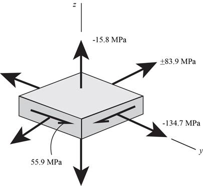
Figure (1)
Substitute
Substitute
The value of
Substitute
Thus, the factor of safety for outer radius is
Want to see more full solutions like this?
Chapter 5 Solutions
Shigley's Mechanical Engineering Design (McGraw-Hill Series in Mechanical Engineering)


- A compound cylinder is made by shrinking a jacket with an outer diameter of 200 mm on a hollow cylinder with diameter of 100 mm and 150 mm. When the compound cylinder is subjected to an internal pressure of 35MNm-2, the maximum circumferential stress in both cylinders is the same. Calculate the maximum stress developed at the internal diameter of the jacket.arrow_forwardA cylindrical steel pressure vessel has hemispherical emd caps. The inner radiuos of the vessel is 24 in anf the wall thickness is constant at o.25 in. When the vessel is presseured to 125 psi determine the following. A. The stresses of the cylinder r and hemispgerical caps. B. Based from the allowable working pressure of the blvessel solved in item a, if the pressure is increased to 250 psi what shall be the uniform thickness of the tankarrow_forwardThe shear stresses t in a rectangular beam arc given by Eq. (5-43): in which Fis the shear force, / is the moment of inertia of the cross-sectional area, /lis the height of the beam, and i] is the distance from the neutral axis to the point where the shear stress is being determined (Fig. 5-32). By integrating over the cross-sectional area, show that the resultant of the shear stresses is equal to the shear force V.arrow_forward
- Repeat Problem 3.3-1, but now use a circular tube with outer diameter d0= 2.5 in. and inner diameter di= 1.5 in.arrow_forwardThe hollow drill pipe for an oil well (sec figure) is 6,2 in. in outer diameter and 0.75 in. in thickness. Just above the bit, the compressive force in the pipe (due to the weight of the pipe) is 62 kips and the torque (due to drilling) is 185 kip-in. Determine the maximum tensile, compressive, and shear stresses in the drill pipe.arrow_forward7.An exhaust fan fitted with 900 mm diameter pulley is driven by a flat belt from a 30 kW, 950 r.p.m. squirrel cage motor. The pulley on the motor shaft is 250 mm in diameter and the centre distance between the fan and motor is 2.25 m. The belt is 100 mm wide with a coefficient of friction of 0.25. If the allowable stress in the belt material is not to exceed 2 MPa, determine the necessary thickness of the belt and its total length. Take centrifugal force effect into consideration for density of belt being 950 kg/m3. [arrow_forward
- The cover of a cylindrical pressure vessel made of cast iron is shown in fig.1 The inner diameter of the cylinder is 500 mm and the internal pressure is limited to 2MPa. The cover is fixed to the cylinder by means of 16 bolts with a nominal diameter of 20 mm. Each bolt is initially tightened with a preload of 20 KN. The bolts are made of steel FeE250 (S yt = 250 N/ mm 2 ). Assume. E for steel = 207 KN/mm 2 ,E for cast iron = 100 KN/mm 2, E for Zinc = 90 KN/mm 2,Determine the factor of safety for bolts considering the effect of the gasket.arrow_forwardThe uniform 3830 kg bar is supported by a smooth wall at A and by a pin at B that is in double shear. Determine the diameter of the smallest pin that can be used if its working shear stress is 74 MPa. Note: Gravitational acceleration is equal to 9.81 m/s2 LAB=10 m; L1=6 m.arrow_forwardThe connecting rod of a four stroke cycle Diesel engineis of circular section and of length 550 mm. The diameter and stroke of the cylinder are 150 mm and240 mm respectively. The maximum combustion pressure is 4.7 N/mm2. Determine the diameter ofthe rod to be used, for a factor of safety of 3 with a material having a yield point of 330 MPa.Find also the maximum bending stress in the connecting rod due to whipping action if the engine runsat 1000 r.p.m. The specific weight of the material is 7800 kg/m3. [Ans. 33.2 mm ; 48 MPa]arrow_forward
- SS 304 steel shaft is 3 m long and has an outer diameter of60 mm. When it is rotating at 60 rad/s, it transmits 30 kWof power from the engine to the generator. Determine thefollowing: a. The smallest thickness of the shaft if the allowableshear stress is 150 MPa and the shaft is restricted notto twist more than 0.08 rad. Use G for steel = 83 GPa. b. The percentage savings in weight had the generatorutilized a solid shaft. Assume same material, length andtorque capacity.arrow_forwardA steel shaft 3 m long is transmitting 1 MW at 240 rev/min. The working conditions to be satisfiedby the shaft are: (a) the shaft must not twist more than 0.02 radian on a length of 10 diameters.(b) the working stress must not exceed 60 MN/m2. If the modulus of rigidity of steel is 80 GN/m2. what is: (i) the diameter of the shaft required.(ii)the actual working stress. (iii) the angle of twist of the 3 m length.[Ans: 150 mm; 60 MN/m2 ; 0.030 rad]arrow_forwardA cylindrical pressure vessel has an inner diameter of 5 ft and a thickness of 3/4 in. The stress capacity of the pressure vessel is 25ksi. If a safety factor of 1.2 is required for the design, determine the maximum internal pressure (in psi) it can sustain. A-36 steel with the following properties: Modulus of Elasticity, E = 29x10^3 ksi or 200 GPa Shear Modulus/Modulus of Rigidity, G = 11.5x10^3 ksi or 79.3 GPa Poisson's Ratio, nu = 0.260 Temperature Coefficient for thermal expansion, a = 6.6x10^-6/°F or 11.7x10^-6/°Carrow_forward
 Mechanics of Materials (MindTap Course List)Mechanical EngineeringISBN:9781337093347Author:Barry J. Goodno, James M. GerePublisher:Cengage Learning