Vector Mechanics for Engineers: Statics
12th Edition
ISBN: 9781259977268
Author: Ferdinand P. Beer, E. Russell Johnston Jr., David Mazurek
Publisher: McGraw-Hill Education
bartleby

Concept explainers

bartleby

Videos

Textbook Question
Book Icon
Chapter 5.3, Problem 5.80P

The cross section of a concrete dam is as shown. For a 1-ft-wide dam section, determine (a) the resultant of the reaction forces exerted by the ground on the base AB of the dam, (b) the point of application of the resultant of part a, (c) the resultant of the pressure forces exerted by the water on the face BC of the dam.
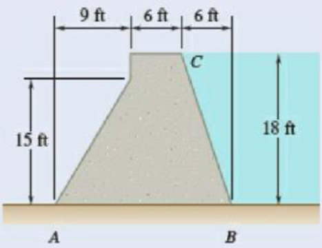
Chapter 5.3, Problem 5.80P, The cross section of a concrete dam is as shown. For a 1-ft-wide dam section, determine (a) the

Fig. P5.80

(a)

Expert Solution
Check Mark
To determine

The reaction force exerted by the ground on the base of the concrete dam.

Answer to Problem 5.80P

The resultant reaction forces acts on the base of the dam is H=10.11kips and V=37.8kips acts in the upward direction.

Explanation of Solution

Given that the width of the dam section w is 1ft. The height of the dam at the point C is h=18ft.

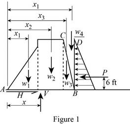
The free-body diagram consists of a 1ft thick section of the dam and the triangular section of water above the dam is shown in the Figure 1.

Vector Mechanics for Engineers: Statics, Chapter 5.3, Problem 5.80P , additional homework tip  1

The wide length of the top section of dam is represented as x1, the distance from the base to the center of the dam is x2, the distance from the base to the point C is x3, and the distance from the base to the point D is x4. Other forces acting on the free body are the weight of the dam represented by the weights of its components are W1, W2, and W3, the weight of the water is W4, and the resultant pressure forces exerted on section BD by the water is P.

Write the equation for weight force of the dam.

W=γV (I)

Here, the weight of the dam is W, specific weight of the object is γ, and the volume of the triangular section of the water above the dam is V.

Replace 1/2lwh for V in the equation (I).

W=γ12lwh

Here, the width of the dam section is w, the length of the surface is l, and the height of the dam is h.

Write the equation for the weight of the dam represented by the weights of its components. W1=γC12l1wh1

Here, the weight of the dam by the components of fist section is W1, specific weight of the concrete is γC, the wide length of the top section of dam is represented as l1, and the height of the dam from the ground to cross section of dam is h1.

Substitute 150lb/ft3 for γC, 9ft for l1, 1ft for w, and 15ft for h1.

W1=(150lb/ft3)[12(9ft)(15ft)(1ft)]=10,125lb

Write the equation for the weight of the dam represented in the triangular section.

W2=γC12l2wh2

Here, the weight of the dam by the components of second section is W2, specific weight of the concrete is γC, the wide length of the triangular section of dam is represented as l2, and the height of the dam from the ground is h2.

Substitute 150lb/ft3 for γC, 6ft for l2, 1ft for w, and 18ft for h2.

W2=(150lb/ft3)[(6ft)(18ft)(1ft)]=16,200lb

Write the equation for the weight of the dam represented by the weights of its components.

W3=γC12l3wh3

Here, the weight of the dam by the components of third section is W3, specific weight of the concrete is γC, the wide length of the triangular section of dam is represented as l3, and the height of the dam from the ground is h3.

Substitute 150lb/ft3 for γC, 6ft for l3, 1ft for w, and 18ft for h3.

W3=(150lb/ft3)[12(6ft)(18ft)(1ft)]=8100lb

Write the equation for the weight of the dam represented by the weights of its components.

W4=γ12l4wh4

Here, the weight of the dam by the components of fourth section is W4, specific weight of fresh water is γ, the wide length of the triangular section of dam is represented as l4, and the height of the dam from the ground is h4.

Substitute 62.4lb/ft3 for γ, 6ft for l4, 1ft for w, and 18ft for h4.

W4=(62.4lb/ft3)[12(6ft)(18ft)(1ft)]=3369.6lb

Write the equation of the force pressure exerted by the ground on the base of the dam.

P=12Ap (II)

Here, the reaction force exerted on the dam is P, cross section area of the dam is A, and the pressure of the water is p.

Replace γh for p and hw for A in equation (II).

P=12(hw)(γh) (III)

Write the equilibrium equation for the section of dam acts along x axis (Refer Fig 1).

Fx=0HP=0 (IV)

Here, the reaction force exerted by the ground on the base AB of the dam is H.

Write the equilibrium equation for the section of beam acts along y axis and then calculate the reaction force (Refer Fig 1).

Fy=0VW1W2W3W4=0 (V)

Here, the reaction force exerted by the ground on the base AB of the dam is V.

Conclusion:

Substitute 62.4lb/ft3 for γ, 1ft for w, and 18ft for h in equation (III) and solve for P.

P=12[(18ft)(1ft)][(62.4lb/ft3)(18ft)]=10,108.8lb

Substitute 10,108.8lb for P in equation (IV) and solve for H.

H10,108.8lb=0H=10,108.8lb(1kips1000lb)=10.1088kips10.11kips

Substitute 10,125lb for W1, 16,200lb for W2, 8100lb for W3, and 3369.6lb for W4 in equation (V) and solve for V.

V10,125lb16,200lb8100lb3369.6lb=0V37794.6lb=0V=37794.6lb

Convert the above reaction force value into kips.

V=37,795lb(1kips1000lb)=37.795kips37.8kips

Therefore, the resultant reaction forces acts on the base of the dam is H=10.11kips and V=37.8kips acts in the upward direction.

(b)

Expert Solution
Check Mark
To determine

The point of forces acts on the base AB of the dam from the resultant of part a.

Answer to Problem 5.80P

The point in which the forces acts on the base AB of the dam is x=10.48ft.

Explanation of Solution

The distance from the base of the dam to the point A  is x1=6ft.

The distance from the base of the dam to the mid part is.

x2=(9+3)ft=12ft

The distance from the base of the dam to the point C (Refer fig 1) is.

x3=(15+2)ft=17ft

The distance from the base of the dam to the total path is.

x4=(15+4)ft=19ft

Write the equilibrium equation for the section on the base AB of the dam and calculate the moment labeled at point A (Refer Fig 1).

MA=0xVW1x1W2x2W3x3W4x4+Pl=0 (VI)

Here, the different section of the dam is represented as x1, x2, x3, and x4.

Conclusion:

Substitute 10,125lb for W1, 16,200lb for W2, 8100lb for W3, 3369.6lb for W4, 37794.6lb for V, 6ft for x1, 12ft for x2, 17ft for x3, 10,108.8lb for P, 6ft for l, and 19ft for x4 in equation (VI) and to solve x.

{x(37794.6lb)(10,125lb)(6ft)(16,200lb)(12ft)(8100lb)(17ft)(3369.6lb)(19ft)+(10,108.8lb)(6ft)=0x(37794.6lb)(60750lbft)(194400lbft)(137700lbft)(64022.4lbft)+(60652.8lbft)=0x(37794.6lb)(456872.4lbft)+(60652.8lbft)=0}

Solve the above equation for x.

x(37794.6lb)(396219.6lbft)=0x(37794.6lb)=(396219.6lbft)x=10.48ft

Therefore, the point in which the forces acts on the base AB of the dam is x=10.48ft.

(c)

Expert Solution
Check Mark
To determine

The resultant pressure force exerted by the water on the face BC of the dam.

Answer to Problem 5.80P

The resultant pressure force exerted by the water on the face BC of the dam is R=10.66kips at the angle of 18.43°.

Explanation of Solution

The free body diagram of the water section BCD in the dam as shown in figure 2:

Vector Mechanics for Engineers: Statics, Chapter 5.3, Problem 5.80P , additional homework tip  2

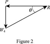
Write the equilibrium equation for the s resultant pressure force exerted by the water on the face BC of the dam (Refer Fig 2).

F=0R=P2+W42 (VII)

Here, the resultant pressure force exerted by the water on the dam is R.

Solve for the angle of resultant force exerted by the water on the dam by using trigonometric relation (Refer fig 2).

tanθ=oppadjθ=tan1(W4P) (VIII)

Conclusion:

Substitute 3369.6lb for W4 and 10,108.8lb for P in equation (VII) and to solve for R.

R=(10,108.8lb)2+(3369.6lb)2=10655.6lb(1kips1000lb)=10.66kips

Substitute 3369.6lb for W4 and 10,108.8lb for P in equation (VIII) and to solve for θ.

θ=tan1(3369.6lb10,108.8lb)=18.43°

Therefore, the resultant pressure force exerted by the water on the face BC of the dam is R=10.66kips at the angle of 18.43°.

Want to see more full solutions like this?

Subscribe now to access step-by-step solutions to millions of textbook problems written by subject matter experts!
Students have asked these similar questions
Two forces are applied as shown to a hook support. Knowing that the magnitude of P is 35 N, determine by trigonometry (a) the required angle α if the resultant R of the two forces applied to the support is to be horizontal, (b) the corresponding magnitude of R.
A steel tank is to be positioned in an excavation. Knowing that the magnitude of P is 500 lb, determine by trigonometry (a) the required angle a if the resultant R of the two forces applied at A is to be vertical, (b) the corresponding magnitude of R.
Two forces P and Q are applied to the lid of a storage bin as shown. Knowing that P= 60 N and Q= 48 N, determine by trigonometry the magnitude and direction of the resultant of the two forces.

Chapter 5 Solutions

Vector Mechanics for Engineers: Statics

Ch. 5.1 - Locate the centroid of the plane area shown.Ch. 5.1 - Locate the centroid of the plane area shown.Ch. 5.1 - Locate the centroid of the plane area shown.Ch. 5.1 - Locate the centroid of the plane area shown.Ch. 5.1 - Locate the centroid of the plane area shown.Ch. 5.1 - PROBLEM 5.16 Determine the y coordinate of the...Ch. 5.1 - Show that as r1 approaches r2, the location of the...Ch. 5.1 - For the area shown, determine the ratio a/b for...Ch. 5.1 - For the semiannular area of Prob. 5.12, determine...Ch. 5.1 - A built-up beam is constructed by nailing seven...Ch. 5.1 - The horizontal x axis is drawn through the...Ch. 5.1 - The horizontal x-axis is drawn through the...Ch. 5.1 - PROBLEM 5.23 The first moment of the shaded area...Ch. 5.1 - A thin, homogeneous wire is bent to form the...Ch. 5.1 - A thin, homogeneous wire is bent to form the...Ch. 5.1 - A thin, homogeneous wire is bent to form the...Ch. 5.1 - A thin, homogeneous wire is bent to form the...Ch. 5.1 - The homogeneous wire ABC is bent into a...Ch. 5.1 - The frame for a sign is fabricated from thin, flat...Ch. 5.1 - The homogeneous wire ABCD is bent as shown and is...Ch. 5.1 - The homogeneous wire ABCD is bent as shown and is...Ch. 5.1 - Determine the distance h for which the centroid of...Ch. 5.1 - Knowing that the distance h has been selected to...Ch. 5.2 - Determine by direct integration the centroid of...Ch. 5.2 - 5.34 through 5.36 Determine by direct integration...Ch. 5.2 - 5.34 through 5.36 Determine by direct integration...Ch. 5.2 - 5.37 through 5.39 Determine by direct integration...Ch. 5.2 - 5.37 through 5.39 Determine by direct integration...Ch. 5.2 - 5.37 through 5.39 Determine by direct integration...Ch. 5.2 - 5.40 and 5.41 Determine by direct integration the...Ch. 5.2 - 5.40 and 5.41 Determine by direct integration the...Ch. 5.2 - Determine by direct integration the centroid of...Ch. 5.2 - 5.43 and 5.44 Determine by direct integration the...Ch. 5.2 - 5.43 and 5.44 Determine by direct integration the...Ch. 5.2 - 5.45 and 5.46 A homogeneous wire is bent into the...Ch. 5.2 - 5.45 and 5.46 A homogeneous wire is bent into the...Ch. 5.2 - A homogeneous wire is bent into the shape shown....Ch. 5.2 - 5.48 and 5.49 Determine by direct integration the...Ch. 5.2 - 5.48 and 5.49 Determine by direct integration the...Ch. 5.2 - Determine the centroid of the area shown in terms...Ch. 5.2 - Determine the centroid of the area shown when a =...Ch. 5.2 - Determine the volume and the surface area of the...Ch. 5.2 - Determine the volume and the surface area of the...Ch. 5.2 - Determine the volume and the surface area of the...Ch. 5.2 - Determine the volume and the surface area of the...Ch. 5.2 - Determine the volume of the solid generated by...Ch. 5.2 - Verify that the expressions for the volumes of the...Ch. 5.2 - Knowing that two equal caps have been removed from...Ch. 5.2 - Three different drive belt profiles are to be...Ch. 5.2 - Determine the capacity, in liters, of the punch...Ch. 5.2 - Determine the volume and total surface area of the...Ch. 5.2 - Determine the volume and weight of the solid brass...Ch. 5.2 - Determine the total surface area of the solid...Ch. 5.2 - Determine the volume of the brass collar obtained...Ch. 5.2 - The shade for a wall-mounted light is formed from...Ch. 5.3 - 5.66 and 5.67 For the beam and loading shown,...Ch. 5.3 - 5.66 and 5.67 For the beam and loading shown,...Ch. 5.3 - 5.68 through 5.73 Determine the reactions at the...Ch. 5.3 - 5.68 through Determine the reactions at the beam...Ch. 5.3 - 5.68 through 5.73 Determine the reactions at the...Ch. 5.3 - 5.68 through Determine the reactions at the beam...Ch. 5.3 - 5.68 through 5.73 Determine the reactions at the...Ch. 5.3 - 5.68 through 5.73 Determine the reactions at the...Ch. 5.3 - Determine (a) the distance a so that the vertical...Ch. 5.3 - Determine (a) the distance a so that the reaction...Ch. 5.3 - Determine the reactions at the beam supports for...Ch. 5.3 - Determine (a) the distributed load w0 at the end D...Ch. 5.3 - The beam AB supports two concentrated loads and...Ch. 5.3 - For the beam and loading of Prob. 5.78, determine...Ch. 5.3 - The cross section of a concrete dam is as shown....Ch. 5.3 - The cross section of a concrete dam is as shown....Ch. 5.3 - The dam for a lake is designed to withstand the...Ch. 5.3 - The base of a dam for a lake is designed to resist...Ch. 5.3 - Prob. 5.84PCh. 5.3 - Prob. 5.85PCh. 5.3 - The 3 4-m side AB of a tank is hinged at its...Ch. 5.3 - The 3 4-m side of an open tank is hinged at its...Ch. 5.3 - A 0.5 0.8-m gate AB is located at the bottom of a...Ch. 5.3 - A 0.5 0.8-m gate AB is located at the bottom of a...Ch. 5.3 - A 4 2-ft gate is hinged at A and is held in...Ch. 5.3 - Fig. P5.90 5.91 Solve Prob. 5.90 if the gate...Ch. 5.3 - A prismatically shaped gate placed at the end of a...Ch. 5.3 - A prismatically shaped gate placed at the end of a...Ch. 5.3 - A long trough is supported by a continuous hinge...Ch. 5.3 - The square gate AB is held in the position shown...Ch. 5.4 - Consider the composite body shown. Determine (a)...Ch. 5.4 - A cone and a cylinder of the same radius a and...Ch. 5.4 - Determine the location of the center of gravity of...Ch. 5.4 - Prob. 5.99PCh. 5.4 - For the stop bracket shown, locate the x...Ch. 5.4 - Fig. P5.100 and P5.101 5.101 For the stop bracket...Ch. 5.4 - Prob. 5.102PCh. 5.4 - Prob. 5.103PCh. 5.4 - For the machine element shown, locate the y...Ch. 5.4 - For the machine element shown, locate the x...Ch. 5.4 - 5.106 and 5.107 Locate the center of gravity of...Ch. 5.4 - 5.106 and 5.107 Locate the center of gravity of...Ch. 5.4 - A corner reflector for tracking by radar has two...Ch. 5.4 - A wastebasket, designed to fit in the corner of a...Ch. 5.4 - An elbow for the duct of a ventilating system is...Ch. 5.4 - A window awning is fabricated from sheet metal...Ch. 5.4 - Locate the center of gravity of the sheet-metal...Ch. 5.4 - Locate the center of gravity of the sheet-metal...Ch. 5.4 - A thin steel wire with a uniform cross section is...Ch. 5.4 - The frame of a greenhouse is constructed from...Ch. 5.4 - Locate the center of gravity of the figure shown,...Ch. 5.4 - Prob. 5.117PCh. 5.4 - A scratch awl has a plastic handle and a steel...Ch. 5.4 - PROBLEM 5.117 A bronze bushing is mounted inside a...Ch. 5.4 - PROBLEM 5.120 A brass collar, of length 2.5 in.,...Ch. 5.4 - PROBLEM 5.121 The three legs of a small...Ch. 5.4 - Prob. 5.122PCh. 5.4 - Determine by direct integration the values of x...Ch. 5.4 - Prob. 5.124PCh. 5.4 - PROBLEM 5.125 Locate the centroid of the volume...Ch. 5.4 - Prob. 5.126PCh. 5.4 - Prob. 5.127PCh. 5.4 - PROBLEM 5.128 Locate the centroid of the volume...Ch. 5.4 - PROBLEM 5.129 Locate the centroid of the volume...Ch. 5.4 - Show that for a regular pyramid of height h and n...Ch. 5.4 - PROBLEM 5.131 Determine by direct integration the...Ch. 5.4 - PROBLEM 5.132 The sides and the base of a punch...Ch. 5.4 - Locate the centroid of the section shown, which...Ch. 5.4 - Locate the centroid of the section shown, which...Ch. 5.4 - Determine by direct integration the location of...Ch. 5.4 - Alter grading a lot, a builder places four stakes...Ch. 5 - 5.137 and 5.138 Locate the centroid of the plane...Ch. 5 - 5.137 and 5.138 Locate the centroid of the plane...Ch. 5 - Prob. 5.139RPCh. 5 - Determine by direct integration the centroid of...Ch. 5 - Determine by direct integration the centroid of...Ch. 5 - The escutcheon (a decorative plate placed on a...Ch. 5 - Determine the reactions at the supports for the...Ch. 5 - A beam is subjected to a linearly distributed...Ch. 5 - A tank is divided into two sections by a 1 1-m...Ch. 5 - Determine the y coordinate of the centroid of the...Ch. 5 - An 8-in.-diameter cylindrical duct and a 4 8-in....Ch. 5 - Three brass plates are brazed to a steel pipe to...
Knowledge Booster
Background pattern image
Mechanical Engineering
Learn more about
Need a deep-dive on the concept behind this application? Look no further. Learn more about this topic, mechanical-engineering and related others by exploring similar questions and additional content below.
Similar questions
SEE MORE QUESTIONS
Recommended textbooks for you
Text book image
Elements Of Electromagnetics
Mechanical Engineering
ISBN:9780190698614
Author:Sadiku, Matthew N. O.
Publisher:Oxford University Press
Text book image
Mechanics of Materials (10th Edition)
Mechanical Engineering
ISBN:9780134319650
Author:Russell C. Hibbeler
Publisher:PEARSON
Text book image
Thermodynamics: An Engineering Approach
Mechanical Engineering
ISBN:9781259822674
Author:Yunus A. Cengel Dr., Michael A. Boles
Publisher:McGraw-Hill Education
Text book image
Control Systems Engineering
Mechanical Engineering
ISBN:9781118170519
Author:Norman S. Nise
Publisher:WILEY
Text book image
Mechanics of Materials (MindTap Course List)
Mechanical Engineering
ISBN:9781337093347
Author:Barry J. Goodno, James M. Gere
Publisher:Cengage Learning
Text book image
Engineering Mechanics: Statics
Mechanical Engineering
ISBN:9781118807330
Author:James L. Meriam, L. G. Kraige, J. N. Bolton
Publisher:WILEY
Types Of loads - Engineering Mechanics | Abhishek Explained; Author: Prime Course;https://www.youtube.com/watch?v=4JVoL9wb5yM;License: Standard YouTube License, CC-BY