
Videos
The switch in the bottom loop of Fig. P6.1 is closed at t = 0 and then opened at a later time t1. What is the direction of the current I in the top loop (clockwise or counterclockwise) at each of these two times?
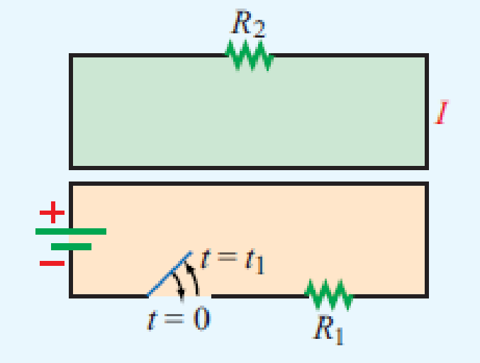
Figure P6.1 Loops of Problem 6.1.
The direction of the current
Answer to Problem 1P
The current in the top loop will be in counter-clockwise direction.
Explanation of Solution
Given data:
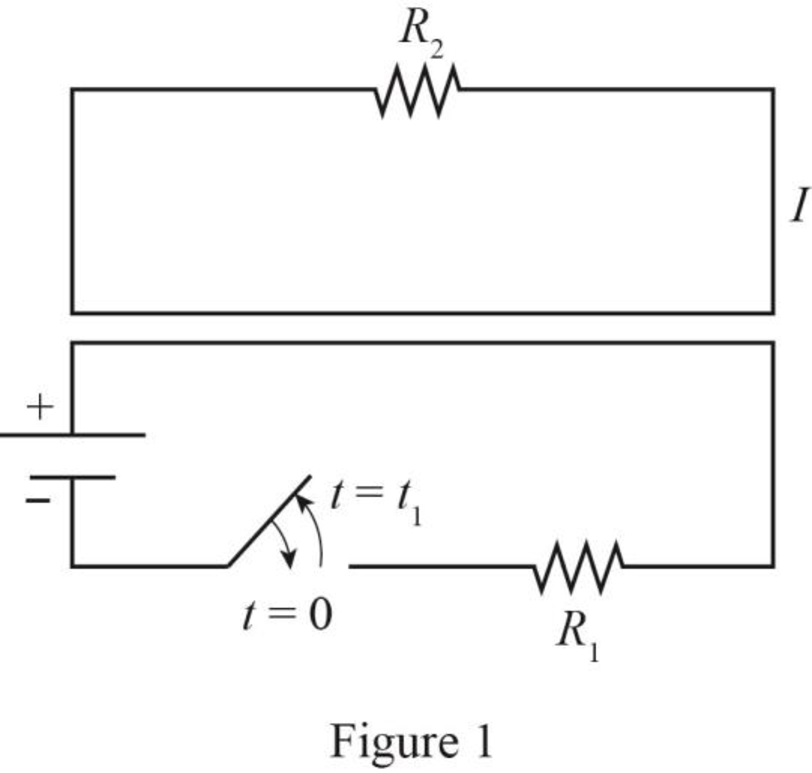
The required diagram is drawn as shown in Figure 1.
Calculation:
The required diagram is drawn as shown in Figure 2 at
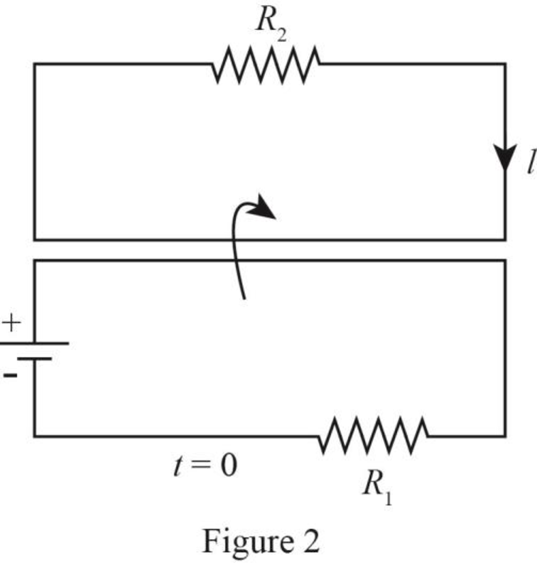
It is observed that at
Hence, the current in the top loop is also momentarily clockwise direction.
From Figure 1, it is observed that there is no current flow in the bottom loop because switch is open. Due to this, there is a decrement of the flux in the secondary loop and if flux decreases then the direction of current will be reversed.
Hence, the current in the top loop will be in counter-clockwise direction.
Conclusion:
Therefore, the current in the top loop will be in counter-clockwise direction.
Want to see more full solutions like this?
Chapter 6 Solutions
Fundamentals Of Applied Electromagnetics
Additional Engineering Textbook Solutions
Introductory Circuit Analysis (13th Edition)
Electrical Engineering: Principles & Applications (7th Edition)
Foundation Design: Principles and Practices (3rd Edition)
Thinking Like an Engineer: An Active Learning Approach (4th Edition)
Software Engineering (10th Edition)
Starting Out with C++ from Control Structures to Objects (9th Edition)


- The voltage at the terminals of the 200 μH inductor in Fig. P6.2(a) is shown in Fig. P6.2(b). The inductor current i is known to be zero for t≤0. 1. Derive the expressions for i for t≥0. 2. Sketch i versus t for 0≤t≤∞.arrow_forwardTwo coaxial conducting cylinders are located at ρ = 2 cm and ρ = 4 cm in free space and have a length of 100 m. The region between the cylinders contains a layer of dielectric from ρ = 2 cm to ρ = 3.69 cm with εr = 2. The capacitance in nF is?arrow_forwardThe equation for the voltage ?(?) across a capacitor at time ? is?(?)=1?(∫?(?)???0+?0)Where ?(?) is the current passing through the capacitor, and ?0 is the initial charge. Consider a capacitor with ?=1?? and ?0=0. If ?(?)=0.1(0.2+sin0.5?) A, find ?(?) for ?=0.5 sec.arrow_forward
- Only by doing symmetry analysis, without calculating the integrals, deduce which components of the electric field cancel, explain why and how the distribution should be so that this would not happen.arrow_forwardA capacitive sensor consists of two parallel plates in air. the plates being (40 mm ) square and separated by a distance of(1mm) . A sheet of dielectric material of thickness (1mm ) and (40 mm) square can slide between the plates. The dielectric constant of the materialis (9) and that for air may be assumed as (1) . Determine the capacitance of the sensor when the sheet has been displaced so that only half of itis between the capacitor plates Knowing that the permittivity of free space (8 .85 pFim).arrow_forwardA cylindrical capacitor is made of two concentric conducting cylinders. The inner cylinder has radius R1 = 19 cm and carries a uniform charge per unit length of λ = 30 μC/m. The outer cylinder has radius R2 = 25 cm and carries an equal but opposite charge distribution as the inner cylinder. a. Use Gauss’ Law to write an equation for the electric field at a distance R1 < r < R2 from the center of the cylinders. Write your answer in terms of λ, r, and e0. E= b. Write an equation for the energy density due to the electric field between the cylinders in terms of λ, r, and e0. u = c. Consider a thin cylindrical shell of thickness dr and radius R1 < r < R2 that is concentric with the cylindrical capacitor. Write an equation for the total energy per unit length contained in the shell in terms of λ, r, dr, and ε0. dU/l = d. Calculate the energy stored per unit length in the capacitor in units of joules per meter. U/l = e. Calculate the electric potential difference between…arrow_forward
- Derive the capacitance formula for the coaxial capacitor starting with Laplace’s equation. The voltage at the inner conductor is Vo and the outer conductor is 0 V. The formula obtained will match equation 6.28 in the book.arrow_forwardAn infinitely large flat surface has a surface density of electric charge. The surface moves with constant velocity in a parallel direction. Show that the differential version of the Poynting theorem holds at all points above and below the surface.arrow_forwardSuppose a capacitor consists of two coaxial thin cylindrical conductors. The inner cylinder of radius ra has a charge of +Q, while the outer cylinder of radius rb has charge -Q. The electric field E at a radial distance r from the central axis is given by the function: E = αe-r/a0 + β/r + b0 where alpha (α), beta (β), a0 and b0 are constants. Find an expression for its capacitance. First, let us derive the potential difference Vab between the two conductors. The potential difference is related to the electric field by: V subscript a b end subscript equals integral subscript r subscript a end subscript superscript r subscript b end superscript E d r equals negative integral subscript r subscript b end subscript superscript r subscript a end superscript E d r Calculating the antiderivative or indefinite integral , Vab = (-αa0e-r/a0 + β+ b0 )right enclose blank end enclose subscript space r subscript a end subscript superscript space r subscript b end superscript By definition, the…arrow_forward
- A resistor (5 Ω) and capacitor (0.05 F) are joined in series with an electromotive force E(t) = 30 −t V. If there is nocharge on the capacitor at time t = 0, find the ensuing charge on the capacitor at time t. The following lineardifferential equation models the charge on the capacitor, q(t). (check the image) How do I go about solving this?arrow_forwardelaborate upon the physical process that leads to a capacitor charging and discharging at opposite directions? Don't use Chat GPT otherwise i will dislike u.arrow_forwardA parallel plate capacitor with 10 cm2 plates and 0.4 cm distance between two parallel plates contains a medium with Er=3.3 and sigma=4x10⁻⁵ (S/m). A potential difference of 100V is applied between the plates. Accordingly, find the power density in the medium.arrow_forward
 Introductory Circuit Analysis (13th Edition)Electrical EngineeringISBN:9780133923605Author:Robert L. BoylestadPublisher:PEARSON
 Delmar's Standard Textbook Of ElectricityElectrical EngineeringISBN:9781337900348Author:Stephen L. HermanPublisher:Cengage Learning
 Programmable Logic ControllersElectrical EngineeringISBN:9780073373843Author:Frank D. PetruzellaPublisher:McGraw-Hill Education
 Fundamentals of Electric CircuitsElectrical EngineeringISBN:9780078028229Author:Charles K Alexander, Matthew SadikuPublisher:McGraw-Hill Education
 Electric Circuits. (11th Edition)Electrical EngineeringISBN:9780134746968Author:James W. Nilsson, Susan RiedelPublisher:PEARSON
 Engineering ElectromagneticsElectrical EngineeringISBN:9780078028151Author:Hayt, William H. (william Hart), Jr, BUCK, John A.Publisher:Mcgraw-hill Education,