
Concept explainers
Videos
For each configuration in Fig. 6.64, find the voltage sources and/or resistors elements (individual elements, not combinations of elements) that are in parallel.
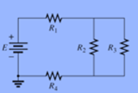
(a)
The individual elements that are in parallel.
Answer to Problem 1P
Resistor
Explanation of Solution
Given:
The given electric network is,
Calculation:
Combinations of elements −
- Resistor
- Voltage source
So, the individual elements that are in parallel are resistor
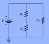
(b)
The individual elements that are in parallel.
Answer to Problem 1P
Voltage source
Explanation of Solution
Given:
The given electric network is,
Calculation:
Combinations of elements −
- Voltage source
- Resistor
The individual elements that are in parallel are voltage source
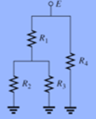
(c)
The individual elements that are in parallel.
Answer to Problem 1P
The individual elements that are in parallelare resistor
Explanation of Solution
Given:
The given electric network is,
Calculation:
Elements that are in parallel are:
- Resistor
- Voltage source
Therefore, number of individual elements that are in parallel areresistor
(d)
The individual elements that are in parallel.
Answer to Problem 1P
Resistor
Explanation of Solution
Calculation:
The given electric network is,
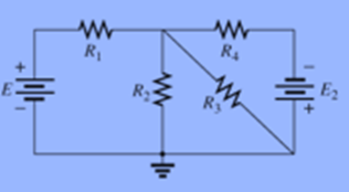
Elements that are in parallel are −
- Resistor
- Resistor
Therefore, number of individual elements that are in parallel are resistor
Want to see more full solutions like this?
Chapter 6 Solutions
Introductory Circuit Analysis; Laboratory Manual For Introductory Circuit Analysis Format: Kit/package/shrinkwrap
Additional Engineering Textbook Solutions
Fundamentals of Applied Electromagnetics (7th Edition)
Electrical Engineering: Principles & Applications (7th Edition)
Java How to Program, Early Objects (11th Edition) (Deitel: How to Program)
Computer Systems: A Programmer's Perspective (3rd Edition)
Elements of Chemical Reaction Engineering (5th Edition) (Prentice Hall International Series in the Physical and Chemical Engineering Sciences)
INTERNATIONAL EDITION---Engineering Mechanics: Statics, 14th edition (SI unit)


- the moisture percentage in timber is increased for the places expose to low temperature Select one: True Falsearrow_forwardDetermine the current drawn from the source in the given circuit in Fig. 6arrow_forwardThe system of using helicopters to work on live power lines is based on the principle that electrical current seeks to flow into the ground. Select one: True Falsearrow_forward
- Graph the circuit in the image and choose a suitable tree. Obtain circuit equations by the method of beam currents. Calculate the powers of the elements, show that the total power is equal to zero.arrow_forwardIn an R-L parallel circuit, ET=240 volts, R=560, and XL=330. Find apparent power.arrow_forwardFor each configuration in Fig. 5.85, find the individual (not combinations of) elements (voltages sources and/or resistors) that are in series. If necessary, use the fact that elements in series have the same current. Simply list those that satisfy the conditions for a series relationship.arrow_forward
- Please solve with hundred percent efficiency Don't use solution which is already on site Write neat and clean by hand solution in the order to get positive feedbackarrow_forwardI want solution of this question the complete solution. and if pdf ofsolvedp book by alexender methew 6edition is available free I will be really gratefularrow_forwardWhat is the function of the circuit? Answer in minimized sum of productsarrow_forward
- 7.solve for VEarrow_forwardSubject: Business process reengineering Q) What is 80/20 rule & where it will be applicable, explain with organization example? Q) Apply 6sigma level of 5S in Iqra university?arrow_forward12/ A junction in a circuit where two or more circuit elements are connected together is known as Node. Select one: True Falsearrow_forward
 Delmar's Standard Textbook Of ElectricityElectrical EngineeringISBN:9781337900348Author:Stephen L. HermanPublisher:Cengage Learning