
Concept explainers
Videos
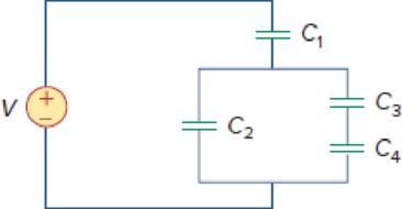
Using Fig. 6.57, design a problem that will help other students better understand how capacitors work together when connected in series and in parallel.
Figure 6.57
Design a problem to make better understand how capacitors work together when connected in series and in parallel using Figure 6.57.
Explanation of Solution
Problem design:
For the circuit in Figure 6.57, determine the voltage across each capacitor and the energy stored in each capacitor.
Formula used:
Write the expression to calculate the energy stored in the capacitor.
Here,
Calculation:
Refer to Figure 6.57 in the textbook. The Figure 6.57 is redrawn as Figure 1 by assuming the voltage and capacitor values.
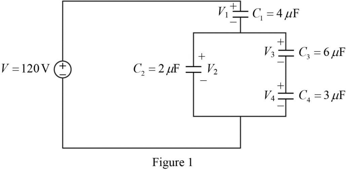
Refer to Figure 1, the capacitors
Write the expression to calculate the equivalent capacitance 1 for the series connected capacitors
Here,
Substitute
The reduced circuit of the Figure 1 is drawn as Figure 2.
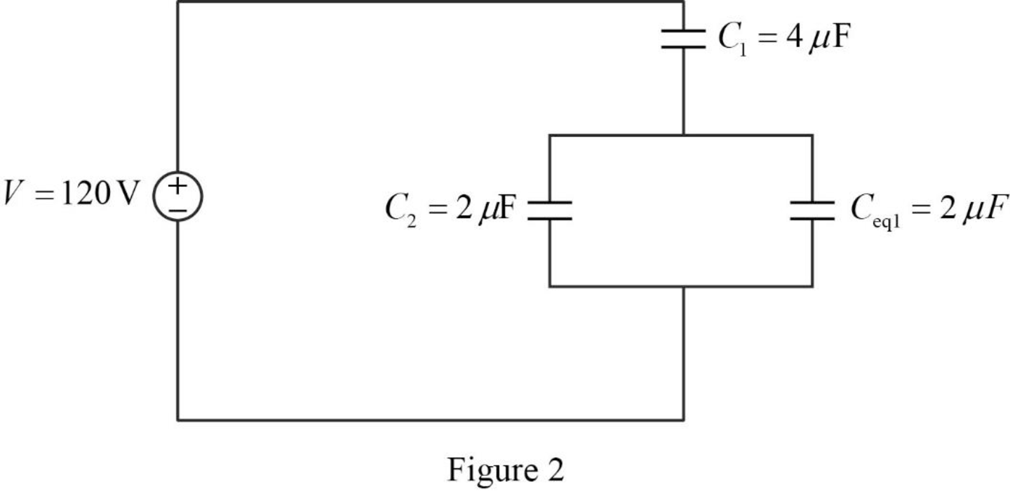
Refer to Figure 2, the capacitors
Write the expression to calculate the equivalent capacitance 2 for the parallel connected capacitors
Here,
Substitute
The reduced circuit of the Figure 2 is drawn as Figure 3.
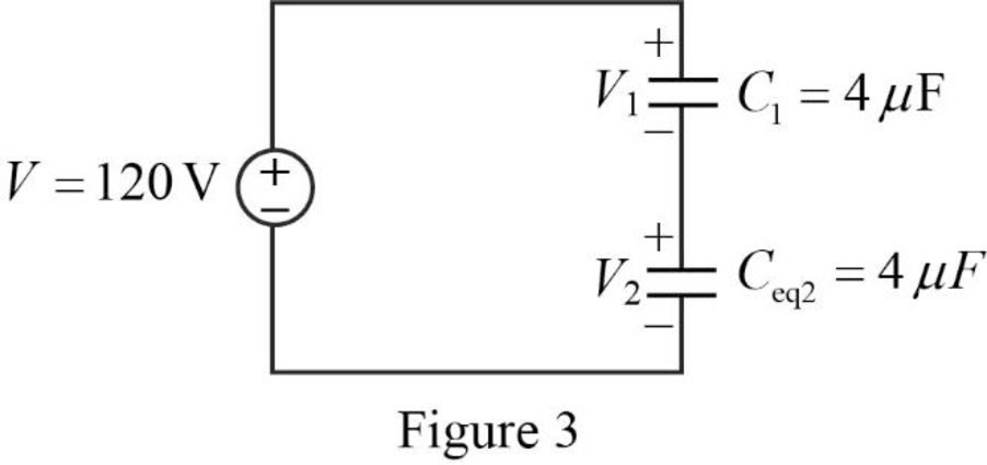
Write the expression to calculate the total applied voltage.
Here,
From the Figure 3, it is clear that the voltage across the capacitors with same capacitance value is equal. Therefore,
Substitute
Simplify the above equation to find
Therefore, from equation (5),
Write the expression to calculate the charge across the capacitor 1.
Here,
Substitute
Write the expression to calculate the charge across the capacitor 2.
Substitute
Refer to Figure 2, the capacitors
The combination of the series connected capacitors
Write the expression to calculate the voltage across the capacitor 3.
Substitute
Write the expression to calculate the voltage across the capacitor 4.
Substitute
Re-write the equation (1) to calculate the energy stored in capacitor
Substitute
Re-write the equation (1) to calculate the energy stored in capacitor
Substitute
Re-write the equation (1) to calculate the energy stored in capacitor
Substitute
Re-write the equation (1) to calculate the energy stored in capacitor
Substitute
Therefore, the value of the voltage across the capacitor 1
Conclusion:
Thus, the problem to make better understand how capacitors work together when connected in series and in parallel using Figure 6.57 is designed.
Want to see more full solutions like this?
Chapter 6 Solutions
Fundamentals of Electric Circuits


- A 767 uF capacitor has an initial voltage, v(0) = 2 V. If the current flowing through the capacitor is i(t) = 11 mA, what is the voltage v(t) across the capacitor, at time t= 40ms? Enter your answer to 3 significant figures.arrow_forwardTwo capacitors are in series with a voltage source of 15 V. If the capacitors are rated at 10 μF and 5 μF respectively, calculate: Equivalent capacitance Equivalent charge, Q1 , and Q2 V1 and V2arrow_forwardTwo capacitors having capacitance values of 8µF and 24µF, respectively, are connected in series and to a 120 volt source. Calculate the charge on, and the voltage across each onearrow_forward
- A parallel plate capacitor with 26 interleaved parallel plates having area of cross section,300mm*500mm and plates are separated by 0.030mm using rubber with dielectric constant 8.5.i. Estimate capacitance and charge stored in the capacitor when a voltage, 250V is applied. [3]ii. What are the modifications required to double the charge storing capacity of given capacitorwithout changing the applied voltage? Justify your answer.arrow_forwardTwo capacitors 10 and 15 μf are in series with two 20 μf capacitors which are connected in parallel to each other. If the emf supplied is 200 V, find (a) the combined capacitance (b) the charge on the 10 μf and (c) the potential drop across the 15 μf capacitorarrow_forward6.35 An inductor has a linear change in current from50 mA to 100 mA in 2 ms and induces a voltage of160 mV. Calculate the value of the inductorarrow_forward
- Two capacitors are in parallel with a voltage source of 15 V. If the capacitors are rated at 10 μF and 5 μF respectively, calculate: Equivalent capacitance V1 and V2 Equivalent charge, Q1 , and Q2arrow_forwardA 20.0 μF capacitor, 25.0 μF capacitor, and a 50.0 μF capacitor areconnected in parallel to a 24.0 V battery. a) What is the equivalent capacitance of the combination?b) What is the charge on each capacitor?c) What is the potential difference across each capacitor?d) What is the energy stored in each capacitor?e) What is the total energy stored?arrow_forwardTwo capacitors of 20 μF and 30 μF are connected in parallel to a 300 volt DC supply. Then find (1) the total capacitance (2) the charge on each capacitor and (3) the energy stored in each capacitor.arrow_forward
- A coil of resistance 1500 ohms and 0.25-H inductance is connected in parallel with a variable capacitance across a 10 V, 8 kHz supply. Calculate the minimum supply current.arrow_forward6 A capacitor is constructed with parallel metal plates, If the plate separation is 2 mm and the capacitance is given to 1 nano Farads, determine the area of the parallel plates of the device. Select one: a. 0.12 square meters b. 0.23 square meters c. 0.27 square meters d. 0.20 square metersarrow_forwardUse realistic inductor values from Appendix H to construct series and parallel combinations of inductors to yield the equivalent inductances specified below. Try to minimize the number of inductors used. Assume that no initial energy is stored in any of the inductors. 1. 8 mH; 2. 45 μH; 3. 180 μH.arrow_forward
 Introductory Circuit Analysis (13th Edition)Electrical EngineeringISBN:9780133923605Author:Robert L. BoylestadPublisher:PEARSON
 Delmar's Standard Textbook Of ElectricityElectrical EngineeringISBN:9781337900348Author:Stephen L. HermanPublisher:Cengage Learning
 Programmable Logic ControllersElectrical EngineeringISBN:9780073373843Author:Frank D. PetruzellaPublisher:McGraw-Hill Education
 Fundamentals of Electric CircuitsElectrical EngineeringISBN:9780078028229Author:Charles K Alexander, Matthew SadikuPublisher:McGraw-Hill Education
 Electric Circuits. (11th Edition)Electrical EngineeringISBN:9780134746968Author:James W. Nilsson, Susan RiedelPublisher:PEARSON
 Engineering ElectromagneticsElectrical EngineeringISBN:9780078028151Author:Hayt, William H. (william Hart), Jr, BUCK, John A.Publisher:Mcgraw-hill Education,