
Concept explainers
Videos
6-37* to 6-46* For the problem specified in the table, build upon the results of the original problem to determine the minimum factor of safety for fatigue based on infinite life, using the modified Goodman criterion. The shaft rotates at a constant speed, has a constant diameter, and is made from cold-drawn AISI 1018 steel.
| Problem Number | Original Problem, Page Number |
| 6-41* | 3–72, 152 |
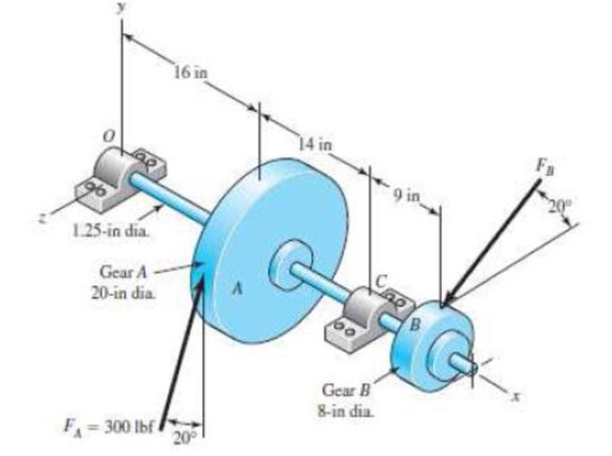
3-72* to 3-73* A gear reduction unit uses the countershaft shown in the figure. Gear A receives power from another gear with the transmitted force FA applied at the 20° pressure angle as shown. The power is transmitted through the shaft and delivered through gear B through a transmitted force FB at the pressure angle shown.
- (a) Determine the force FB assuming the shaft is running at a constant speed.
- (b) Find the bearing reaction forces, assuming the bearings act as simple supports.
- (c) Draw shear-force and bending-moment diagrams for the shaft. If needed, make one set for the horizontal plane and another set for the vertical plane.
- (d) At the point of maximum bending moment, determine the bending stress and the torsional shear stress.
- (e) At the point of maximum bending moment, determine the principal stresses and the maximum shear stress.
The minimum factor of safety for fatigue based on infinite life.
Answer to Problem 41P
The minimum factor of safety for fatigue based on infinite life is
Explanation of Solution
The following figure shows the free body diagram of the gear A.
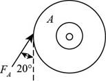
Figure-(1)
The following figure shows the free body diagram of the gear B.
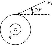
Figure-(2)
Calculate the force
Here, the force acting on pulley
Write the moment about bearing
Here, the reaction force at bearing
Write the equation to balance the forces in
Here, the reaction force at bearing
Write the moment about bearing
Here, the reaction force at bearing
Write the equation to balance the forces in
Here, the reaction force at bearing
Calculate the reaction forces at bearing
Here, the reaction force at bearing
Calculate the reaction forces at bearing
Here, the reaction force at bearing
The calculations for shear force and bending moment diagram in
Calculate the shear force at
Here, the shear force at
Calculate the shear force at
Here, the shear force at
Calculate the shear force at
Here, the shear force at
Calculate the shear force at
Here, the shear force at
Calculate the moment at
Here, the moment at
Calculate the moment at
Here, the moment at
Calculate the moment at
Here, the moment at
Write the net moment at
Here, the net moment at
Write the net moment at
Here, the net moment at
Write the torque transmitted by shaft from
Here, the torque transmitted by shaft from
Calculate the bending stress.
Here, the bending stress is
Calculate the shear stress.
Here, the shear stress is
Calculate the maximum principal stress.
Here, the maximum principal stress is
Calculate the minimum principal stress.
Here, the minimum principal stress is
Calculate the maximum shear stress.
Here, maximum shear stress is
Write the expression for von Mises alternating stress.
Here, the amplitude component of the axial stress is
Write the expression for von Mises mid-range stress.
Here, the mid-range component of the axial stress is
Write the expression for von Mises maximum stress.
Here, the maximum component of the axial stress is
Write the expression for yield factor of safety.
Here, the yield strength of the material is
Write the expression for endurance limit for test specimen.
Here, the minimum tensile strength is
Write the surface factor for the countershaft.
Here, the constants for surface factor are
Write the size factor for the countershaft.
Write the endurance limit at the critical location of the machine part.
Write the modified Goodman equation.
Here, the fatigue factor of safety is
Conclusion:
Substitute
Substitute
Substitute
Substitute
Substitute
Substitute
Substitute
Substitute
Substitute
Substitute
Substitute
Substitute
Substitute
Thus, the shear force and bending moment diagram in
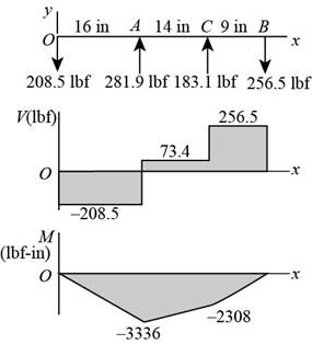
Figure-(3)
Substitute
Substitute
Substitute
Substitute
Substitute
Substitute
Thus, the shear force and bending moment diagram in
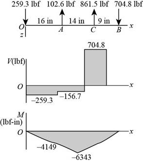
Figure-(4)
Substitute
Substitute
Since,
The critical location is at C.
Substitute
Substitute
Substitute
Substitute
Substitute
Substitute
Substitute
Substitute
Substitute
Refer to the Table A-20 “Deterministic ASTM Minimum Tensile and Yield Strengths for Some Hot-Rolled (HR) and Cold-Drawn (CD) Steels” to obtain the yield strength as
Substitute
Substitute
Refer to Table 6-2 “Parameters for Marin Surface Modification Factor” to obtain
Substitute
Substitute
Substitute
Substitute
Thus, the minimum factor of safety for fatigue based on infinite life is
Want to see more full solutions like this?
Chapter 6 Solutions
Shigley's Mechanical Engineering Design (McGraw-Hill Series in Mechanical Engineering)


- A certain steel shafting material has an ultimate strength of 93 ksi, a notch radius of 0.25 inch, and a stress concentration factor of 2.5 at its pitch. Determine the fatigue-strength reduction factor for a life of 166,077 cycles onlyarrow_forwardThe shaft in the figure is mounted with a gear wheel key. Shaft material 42CrMo4 The weight of the gear on the shaft is 0.9 kg, dimension, surface and notch factors KbK / Kç = 0.83, shaft speed n = 1120 rpm, shaft transmitted power 7.5 kW, force on shaft Fn = F = 2680 N Since the desired safety coefficient is Ssafe = 2; Check the safety of the shaftarrow_forwardThe cold-drawn AISI 1040 steel bar shown in the figure is subjected to an axial load fluctuating between 0kN and 28kN. Estimate the fatigue factor of safety based on achieving infinite life using modified Goodman criterion and the yielding factor of safety. If infinite life is not predicted, estimate the number of cycles to failure.arrow_forward
- The figure shows a section of a shaft made of annealed steel with yield strength of 600 MPa and ultimate tensile strength of 700 MPa. Diameters of the shaft are D=30 mm and d=20 mm. Fillet radius of the shoulder section is 2.5 mm. The shaft is rotating and subjected to steady bending moment of M=51 Nm, steady torsion of T=58 Nm and steady axial load of F=14 kN. The operating temperature of the shaft is 20 ᵒC and reliability is 99%. The shaft has ground surface.Calculate the mean component of the shear stress (in MPa)arrow_forwardThe figure shows a section of a shaft made of annealed steel with yield strength of 600 MPa and ultimate tensile strength of 700 MPa. Diameters of the shaft are D=30 mm and d=20 mm. Fillet radius of the shoulder section is 2.5 mm. The shaft is rotating and subjected to steady bending moment of M=51 Nm, steady torsion of T=58 Nm and steady axial load of F=14 kN. The operating temperature of the shaft is 20 ᵒC and reliability is 99%. The shaft has ground surface. Calculate the alternating component of the normal stress (in MPa). (If there is no alternating component of the normal stress, enter "0" in the answer box)arrow_forwardAn input shaft of a gearbox with motor power P = 7 kW and rotation number n = 1300 rpm. The diameter of an input shaft is d = 20 mm and its material is 16MnCr5. A force of F = 2800 N forces the shaft due to the operation of a gear wheel connected with a wedge on the input shaft. The distances of the gear from the bearings are given as L₁ = 40 mm and L2 = 60 mm. In the most dangerous section, you are required to check the strength according to the S = 3 safety factor. If the section is unsafe in terms of strength, what changes would you make in the design to make it safe? (The surface of the spindle is machined as fine chips, reliability poor Kg = 1.).arrow_forward
- The cold-drawn AISI 1040 Q&T at 205 ◦C steel bar shown in the figure is subjected to a completely reversed axial load fluctuating between 28 kN in compression to 28 kN in tension. Estimate the fatigue factor of safety based on achieving infinite life, and the yielding factor of safety for the following cases. If infinite life is not predicted, estimate the number of cycles to failure.a) for the part given in Fig 2(a) and b) for the part given in Fig. 2 (b) using the same dimensions (W=25mm, r=3mm, the thickness of 10 mm)arrow_forwardA rotating shaft of 25-mm diameter is simply supported by bearing reaction forces R1 and R2. The shaft is loaded with a transverse load of 13 kN as shown in the figure. The shaft is made from AISI 1045 hot-rolled steel. The surface has been machined. Determine a) The minimum static factor of safety based on yielding b) the endurance limit adjusted as necessary with Marin factors c) the minimum fatigue factor of safety based on achieving infinite life d) if the fatigue factor of safety is less than 1, then estimate the life of the part in number of rotationsarrow_forwardThe figure shows a shaft mounted in bearings at A and D and having pulleys at B and C. The forces shown acting on the pulley surfaces represent the belt tensions. The shaft is to be made of AISI 1035 CD steel. The shaft is rotating at speed of 1000 rpm. Find the minimum factor of safety for fatigue based on infinite life. If the life is not infinite, estimate the number of cycles. Be sure to check for yielding. Take shaft diameter to be 1.5 inches.arrow_forward
- A bracket is under a loading condition shown below. It's made from a steel with yield strength (Sy) of 42 ksi and ultimate tensile strength (Sut) of 76 ksi. The diameter is 0.42 in and b = 1.75 in, with the load P fluctuate between 15 lbs (tension) and -5 lbs (compression). Using the modified Goodman or Gerber criterion, determine the fatigue factor of safety based on infinite life. If infinite life is not predicted, estimate the number of cycles to failure. Also check for yielding.arrow_forwardThe shaft shown in the figure is machined from AISI 1040 CD steel. The shaft rotates at 1600 rpm and is supported in rolling bearings at A and B. The applied forces are F1 = 1600 lbf and F2 = 640 lbf. A steady torque of 1600 lbf·in is being transmitted through the shaft between the points of application of the forces. ——————————————- Determine the endurance limit for this material as well as the value after correction for surface finish, sizing, and loading. (You must provide an answer before moving to the next part.) The endurance limit for this material is kpsi. The value after correction for surface finish, sizing, and loading is kpsi.arrow_forwardA Steel shaft is subjected to an end thrust producing a stress of 90 MPa and the minimum shearing stress on the surface arising from torsion is 60 MPa .The yield point stress of the material in simple tension was found to be 300 MPa. calculate the factor of safety of the shaft according to the following theory 1)maximum shear stress theoryarrow_forward
 Elements Of ElectromagneticsMechanical EngineeringISBN:9780190698614Author:Sadiku, Matthew N. O.Publisher:Oxford University Press
 Mechanics of Materials (10th Edition)Mechanical EngineeringISBN:9780134319650Author:Russell C. HibbelerPublisher:PEARSON
 Thermodynamics: An Engineering ApproachMechanical EngineeringISBN:9781259822674Author:Yunus A. Cengel Dr., Michael A. BolesPublisher:McGraw-Hill Education
 Control Systems EngineeringMechanical EngineeringISBN:9781118170519Author:Norman S. NisePublisher:WILEY
 Mechanics of Materials (MindTap Course List)Mechanical EngineeringISBN:9781337093347Author:Barry J. Goodno, James M. GerePublisher:Cengage Learning
 Engineering Mechanics: StaticsMechanical EngineeringISBN:9781118807330Author:James L. Meriam, L. G. Kraige, J. N. BoltonPublisher:WILEY