
(a).
The small-signal transistor parameters
(a).
Answer to Problem 6.14TYU
The values of small-signal parameters are,
Explanation of Solution
Given Information:
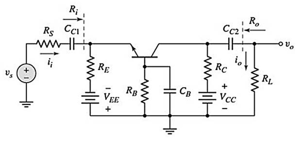
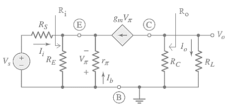
The circuit diagram is shown below.
Calculation:
The coupling and bypass capacitor act like open circuit for DC analysis. The AC voltage source ( vs ) is short circuited for DC analysis.
The modified figure is,
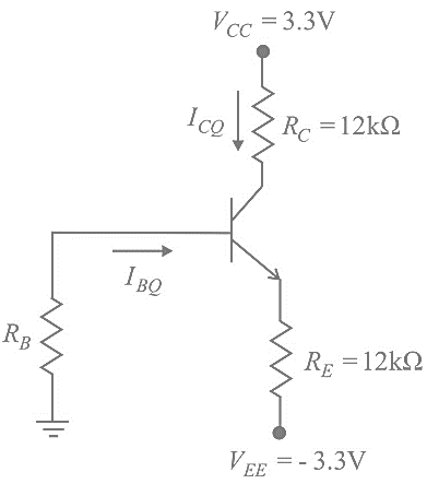
Applying Kirchhoff’s voltage law in base-emitter loop,
Determining the collector current,
Determining the Trans-conductance,
Determining the diffusion resistance
Determining the small-signal transistor output resistance
(b).
The small signal current gain
(b).
Answer to Problem 6.14TYU
The values of current and voltage gain,
Explanation of Solution
Given Information:
The circuit diagram is shown below.

Calculation:
The coupling and bypass capacitors are short circuited for small-signal analysis. The DC voltage source is short circuited for small−signal analysis.
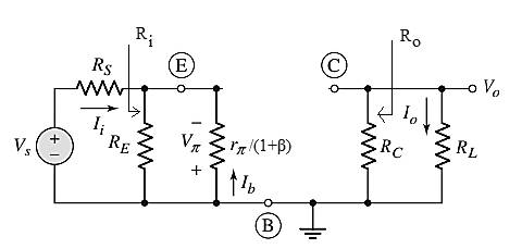
The modified figure is,
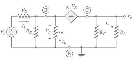
Applying current division rule in output,
Considering input circuit,
Applying current division rule in input,
From equation (1),
Determining the small-signal voltage gain,
Applying voltage division rule in input,
Plugging the value of
(c).
The values of input and output resistance.
(c).
Answer to Problem 6.14TYU
The values of input and output resistance are,
Explanation of Solution
Given Information:
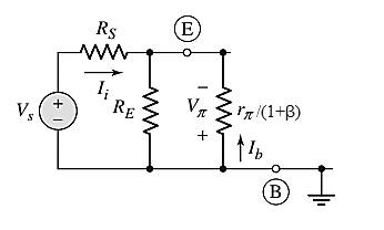
The circuit diagram is,

Calculation:
Considering the small signal equivalent circuit,
The value of input resistance is,
Determining the output resistance,
Want to see more full solutions like this?
Chapter 6 Solutions
Microelectronics: Circuit Analysis and Design

- 1.3 A coaxial cylindrical capacitor is to be designed with an effective length of 10 cm. The capacitor is expected to have a capacitance of 100 pF and to operate at 11 kV, 1000 kHz. Determine the required thickness if the required insulating material is Polytetrafluoroethylene (P.T.F.E.), &r= 2.0, Eb = 250 kV/cm. Allow a factor of safety of 4 and take to = 8.85x10⁻¹² F/m.arrow_forwarddraw a qpsk demodulation circuit using circuit components for instance resistors, capacitors, transistors etcarrow_forwardi find in other explain to this that the answer is Vc+4i(x). ,,,,, but why it's not VL + Vc + 4i(x) explain the answer pleasearrow_forward
- Let vo represent the voltage across the 16 H inductor in the circuit in Fig. 6.29. Assume vo is positive at the dot. As , ig=16−16e−5t A. 1. Can you find vo without having to differentiate the expressions for the currents? Explain. 2. Derive the expression for vo. 3. Check your answer in (b) using the appropriate current derivatives and inductances.arrow_forwardFor a single spine field, treated with 6MV (dmax = 1.5cm) to a depth of 5cm at 100cm SSD. What is the Mayneord F Factor for the following extended SSD setups?a. 110cmb. 120cmc. 130cmd. 140cme. 150cmarrow_forwardDifferential Equation: y′′+6y′+58y=0 describes a series inductor-capacitor-resistor circuit in electrical engineering.The voltage across the capacitor is y (volts). The independent variable is t(seconds). Boundary conditions at t=0 are: y = 6 volts and y′=8 volts/sec . Determine the capacitor voltage at t=0.40seconds . ans:1arrow_forward
- The distance between the plates of a capacitor, which consists of a square plate with a side length of 3 cm, is 2mm. The dielectric coefficient of the insulator is 2. If the maximum electric field that the air can withstand is 2.10 ⁶ V / m, find the maximum load the capacitor can carry.arrow_forwardGiven V(t) = 3(5t + 2)V for 0 ≤ t ≤ 5s, find the current (I(t)) and charge (Q(t)) in capacitor with C = 900nF. Assume the capacitor is initially discharged (Vc(t<0) = 0V)arrow_forwardWhere do we use SCADA in electrical engineering? Can you please explain the basic principle of it and cite some examples? Please provide answer as long as you want, I'll definitely give a like :)arrow_forward
- The current in a 20 mH inductor is known to be i=40 mA,t≤0; i=A1e−10,000t+A2e−40.000tA,t≥0. The voltage across the inductor (passive sign convention) is 28 V at t=0. 1. Find the expression for the voltage across the inductor for t>0. 2. Find the time, greater than zero, when the power at the terminals of the inductor is zero.arrow_forwardA rectangular cathode with the dimensions width = 2.6 mm and length = 30 mm glows at a temperature of 1800K in a vacuum tube. The work function of the cathode is = 2.5 eV and the emission constant is 3E4 . What is the maximum (saturation) current that can be extracted from this cathode? Hint: If you use the Boltzmann constant in eV enter at least 5 significant digits (i.e. use 8.6174E-5 ) State the current in Amp units.arrow_forwardSubject: Electronics Engineering Solve no 6arrow_forward
 Introductory Circuit Analysis (13th Edition)Electrical EngineeringISBN:9780133923605Author:Robert L. BoylestadPublisher:PEARSON
 Delmar's Standard Textbook Of ElectricityElectrical EngineeringISBN:9781337900348Author:Stephen L. HermanPublisher:Cengage Learning
 Programmable Logic ControllersElectrical EngineeringISBN:9780073373843Author:Frank D. PetruzellaPublisher:McGraw-Hill Education
 Fundamentals of Electric CircuitsElectrical EngineeringISBN:9780078028229Author:Charles K Alexander, Matthew SadikuPublisher:McGraw-Hill Education
 Electric Circuits. (11th Edition)Electrical EngineeringISBN:9780134746968Author:James W. Nilsson, Susan RiedelPublisher:PEARSON
 Engineering ElectromagneticsElectrical EngineeringISBN:9780078028151Author:Hayt, William H. (william Hart), Jr, BUCK, John A.Publisher:Mcgraw-hill Education,