The circuit parameters for the circuit in Figure 6.3 are V C C = 3.3 V , V B B = 0.850 V , R B = 180 kΩ , and R C = 15 kΩ . The transistor parameters are β = 120 and V B E (on) = 0.7 V . (a) Determine the Q −point values I C Q and V C E Q . (b) Find the small−signal hybrid− π parameters g m and r π . (c) Calculate the small−signal voltage gain. (Ans. (a) I C Q =0 .1mA , V C E Q = 1.8 V ; (b) g m = 3.846 mA/V , r π = 31.2 kΩ ; (c) A υ = − 8.52 ).
The circuit parameters for the circuit in Figure 6.3 are V C C = 3.3 V , V B B = 0.850 V , R B = 180 kΩ , and R C = 15 kΩ . The transistor parameters are β = 120 and V B E (on) = 0.7 V . (a) Determine the Q −point values I C Q and V C E Q . (b) Find the small−signal hybrid− π parameters g m and r π . (c) Calculate the small−signal voltage gain. (Ans. (a) I C Q =0 .1mA , V C E Q = 1.8 V ; (b) g m = 3.846 mA/V , r π = 31.2 kΩ ; (c) A υ = − 8.52 ).
The circuit parameters for the circuit in Figure 6.3 are
V
C
C
=
3.3
V
,
V
B
B
=
0.850
V
,
R
B
=
180
kΩ
, and
R
C
=
15
kΩ
. The transistor parameters are
β
=
120
and
V
B
E
(on)
=
0.7
V
. (a) Determine the Q−point values
I
C
Q
and
V
C
E
Q
. (b) Find the small−signal hybrid−
π
parameters
g
m
and
r
π
. (c) Calculate the small−signal voltage gain. (Ans. (a)
I
C
Q
=0
.1mA
,
V
C
E
Q
=
1.8
V
; (b)
g
m
=
3.846
mA/V
,
r
π
=
31.2
kΩ
; (c)
A
υ
=
−
8.52
).
(a)
Expert Solution
To determine
The quiescent collector current ICQ and the Q -point value VCEQ for the given transistor.
Answer to Problem 6.1EP
The quiescent collector current ICQ is 0.1 mA and Q -point VCEQ is 1.8 V .
Explanation of Solution
Given:
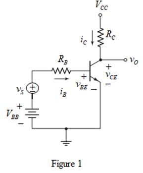
The circuit for common emitter is shown in Figure 1.
The circuit parameters for the transistor circuit shown in Figure 1 are as follows:
VCC=3.3 VRC=15 kΩRB=180 kΩVBE(on)=0.7 VVBB=0.85 V
The value of current gain β is 120 .
Concept used:
The expression for quiescent collector current is written below:
ICQ=βIBQ ...... (1)
The expression for quiescent value VCEQ is written below.
VCEQ=VCC−ICQRC ...... (2)
Calculation:
From DC analysis the ac voltage source is reduced to zero and the equation can be written as,
IBQ=VBB−VB(on)RB ...... (3)
Substitute 0.85 for VBB , 0.7 for VB(on) and 180×103 for RB in equation (3).
IBQ=0.85−0.7180×103=11200 mA
Substitute 120 for β and 11200 for IBQ in equation (1).
ICQ=120⋅11200 mA=110 mA=0.1 mA
Therefore, the quiescent collector current ICQ is 0.1 mA .
Substitute 3.3 for VCC , 0.1×10⁻³ for ICQ and 15×103 for RC in equation (2).
VCEQ=3.3−(0.1×10⁻³)(15×103)=3.3−1.5=1.8 V
Therefore, the Q -point VCEQ is 1.8 V .
Conclusion:
Thus, the quiescent collector current ICQ is 0.1 mA and Q -point VCEQ is 1.8 V .
(b)
Expert Solution
To determine
The transconductance gm and the diffusion resistance rπ for small signal analysis.
Answer to Problem 6.1EP
The transconductance gm is 3.846mA/V and the diffusion resistance rπ is 31.2 kΩ .
Explanation of Solution
Concept used:
The expression for transconductance gm is written below.
gm=ICQVT ...... (4)
Here, VT is thermal voltage and its value is 26 mV .
The expression for diffusion resistance is written below.
rπ=βVTICQ ...... (5)
Calculation:
Substitute 0.1×10⁻³ for ICQ and 26×10−3 for VT in equation (4).
gm=0.1×10−326×10−3=3.846mA/V
Therefore, the transconductance gm is 3.846mA/V .
Substitute 120 for β , 26×10−3 for VT and 0.1×10⁻³ for ICQ in equation (5).
rπ=120(26×10−3)0.1×10−3=31.2×10³Ω
Therefore, the diffusion resistance rπ is 31.2 kΩ .
Conclusion:
Thus, the transconductance gm is 3.846mA/V and the diffusion resistance rπ is 31.2 kΩ .
(c)
Expert Solution
To determine
The value of small signal voltage gain Av .
Answer to Problem 6.1EP
The value of small signal voltage gain Av is −8.52 .
Explanation of Solution
Concept used:
The expression for small signal voltage gain Av is written below.
Av=−(gmRC)⋅(rπrπ+RB) ...... (6)
Calculation:
Substitute 3.846 for gm , 15 for RC , 31.2 for rπ and 180 for RB in equation (6).
Av=−[(3.846)(15)]⋅(31.231.2+180)≈−8.52
Therefore, the voltage gain Av is −8.52 .
Conclusion:
Thus, the value of small signal voltage gain Av is −8.52 .
Want to see more full solutions like this?
Subscribe now to access step-by-step solutions to millions of textbook problems written by subject matter experts!
Trying to solve this MOSFET question but not sure how.(Given Answer:a) Av = -gm (ro|| RD)b)Av = -30.7 Ri = 20 kohm Ro = 7.67 kohm)
draw a qpsk demodulation circuit using circuit components for instance resistors, capacitors, transistors etc
Complete the phrase! The error of a measurement system depends on the non-ideal characteristics of every element in the system. Using calibration techniques we can identify which element in the system have the most dominant non-ideal behavior. We can than devise compensation strategies for t6hese elements which should produce significant reductions in the overall system error. The methods are named .....
Need a deep-dive on the concept behind this application? Look no further. Learn more about this topic, electrical-engineering and related others by exploring similar questions and additional content below.


 Introductory Circuit Analysis (13th Edition)Electrical EngineeringISBN:9780133923605Author:Robert L. BoylestadPublisher:PEARSON
 Delmar's Standard Textbook Of ElectricityElectrical EngineeringISBN:9781337900348Author:Stephen L. HermanPublisher:Cengage Learning
 Programmable Logic ControllersElectrical EngineeringISBN:9780073373843Author:Frank D. PetruzellaPublisher:McGraw-Hill Education
 Fundamentals of Electric CircuitsElectrical EngineeringISBN:9780078028229Author:Charles K Alexander, Matthew SadikuPublisher:McGraw-Hill Education
 Electric Circuits. (11th Edition)Electrical EngineeringISBN:9780134746968Author:James W. Nilsson, Susan RiedelPublisher:PEARSON
 Engineering ElectromagneticsElectrical EngineeringISBN:9780078028151Author:Hayt, William H. (william Hart), Jr, BUCK, John A.Publisher:Mcgraw-hill Education,