
Videos
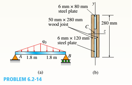
-14 A simply supported composite beam with a 3.6 m span supports a triangularly distributed load of peak intensity q0at mid-span (see figure part a). The beam is constructed of two wood joists, each 50 mm x 280 mm, fastened to two steel plates, one of dimensions 6 mm × 80 mm and the lower plate of dimensions 6 mm x 120mm (see figure part b). The modulus of elasticity for the wood is 11 GPa and for the steel is 210 GPa.
If the allowable stresses are 7 MPa for the wood and 120 MPa for the steel, find the allowable peak load intensity q0maxwhen the beam is bent about the z axis. Neglect the weight of the beam.
The peak maximum load intensity
Answer to Problem 6.2.14P
The peak maximum load intensity
Explanation of Solution
Given Information:
The given figure,
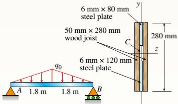
A supported beam with the span of 3.6m supports a load that is triangularly distributed with the peak intensity at the mid span. The two wood joists of the beam each measuring 50mm*280mm that is fastened to steel plates of two that has dimensions of 6mm*80mm and 6mm*120mm. The wood elasticity modulus is 11GPa and for steel it is 210GPa.
By the given equation the neutral axis location is determined,
Where,
Using the figure we have,
The distance between the section 1centroid and composite section neutral axis is,
The distance between the section 2 centroid and composite section neutral axis is,
The distance between the section 3 centroid and composite section neutral axis is,
The distance between the section 4 centroid and composite section neutral axis is,
Section 1 area
Section 2 area
Section 3 area
Section 4 area
Substituting the given values in (1)
Assume the load is symmetric at the span centre. So at point A the reaction is half the total load
The bending moment maximum is seen at the mid span as the symmetric load is at the span centre.
In the diagram the beam at the mid span is cut and the equilibrium cut at the left side is considered. Here M is considered as the bending moment maximum.
The right section moment is given as,
With the help of parallel axis theorem the steel section’s second moment of inertia at the neutral axis is determined.
With the help of parallel axis theorem the wooden section’s second moment of inertia at the neutral axis is determined.
The equation of the flexural stress at the maximum of the steel that has the top layer,
Substituting the values we have,
As the top layer of the steel is compressive the negative sign is given in the equation (2)
The equation of the flexural stress at the maximum of the steel that has the bottom layer,
The equation of the flexural stress at the maximum of the wood that has the top layer,
The equation of the flexural stress at the maximum of the wood that has the bottom layer,
The load with the lowest magnitude is selected from the equations (2), (3), (4), (5)
Conclusion:
Thus, the peak maximum load intensity is calculated by substituting section areas in equation 1.
Want to see more full solutions like this?
Chapter 6 Solutions
Mechanics of Materials (MindTap Course List)


- A hollow box beam is constructed with webs of Douglas-fir plywood and flanges of pine, as shown in the figure in a cross-sectional view. The plywood is 1 in. thick and 12 in. wide; the flanges are 2 in. × 4 in. (nominal size). The modulus of elasticity for the plywood is 1,800,000 psi and for the pine is 1,400,000 psi. If the allowable stresses are 2000 psi for the plywood and 1750 psi for the pine, find the allowable bending moment Mmaxwhen the beam is bent about the z axis. Repeat part (a) if the beam is now bent about its y-axis.arrow_forwardA simple beam that is 18 ft long supports a uniform load of intensity q. The beam is constructed of two C8 x 11.5 sections (channel sections or C-shapes) on either side of a 4 × 8 (actual dimensions) wood beam (see the cross section shown in the figure part a). The modulus of elasticity of the steel (E; = 30,000 ksi) is 20 times that of the wood (Ew). (a) If the allowable stresses in the steel and wood are 12,000 psi and 900 psi, respectively, what is the allowable load qmax Note: Disregard the weight of the beam, and see Table F-3(a) of Appendix F for the dimensions and properties of the C-shape beam. (b) If the beam is rotated 90° to bend about its v axis (see figure part b) and uniform load q = 250 lb/ft is applied, find the maximum stresses trs and crw in the steel and wood, respectively Include the weight of the beam. (Assume weight densities of 35 lb/ft3 and 490 lb/ft3 for the wood and steel, respectively.)arrow_forwardTwo wood beams, each of rectangular cross section (3.0 in. x 4.0 in., actual dimensions), are glued together to form a solid beam with dimensions 6.0 in. x 4.0 in. (sec figure). The beam is simply supported with a span of S ft. What is the maximum moment Mmaxthat may be applied at the left support if the allowable shear stress in the glued joint is 200 psi? (Include the effects of the beams own weight, assuming that the wood weighs 35 lb/ft3.) Repeat part (a) if Mmaxis based on allowable bending stress of 2500 psi.arrow_forward
- Two flat beams AB and CD, lying in horizontal planes, cross at right angles and jointly support a vertical load P at their midpoints (see figure). Before the load P is applied, the beams just touch each other. Both beams are made of the same material and have the same widths. Also, the ends of both beams are simply supported. The lengths of beams AB and CD are LABand LCD, respectively. What should be the ratio tABltCDof the thicknesses of the beams if all four reactions arc to be the same?arrow_forwardA pontoon bridge (see figure) is constructed of two longitudinal wood beams, known as bulks, that span between adjacent pontoons and support the transverse floor beams, which arc called chesses. For purposes of design, assume that a uniform floor load of 7.5 kPa acts over the chesses. (This load includes an allowance for the weights of the chesses and balks.) Also, assume that the chesses are 2.5 m long and that the balks are simply supported with a span of 3.0 m. The allowable bending stress in the wood is 15 MPa. If the balks have a square cross section, what is their minimum required width b^l Repeat part (a) if the balk width is 1.5 b and the balk depth is b; compare the cross-sectional areas of the two designs.arrow_forwardA simple beam thai is IS ft long supports a uni¬form load of intensity a. The beam is constructed of two angle sections, each L (1 × 4 × 1/2, on either side of a 2 in. x 8 in. (actual dimensions! wood beam (see the cross section shown in the figure part a]. The modulus of elasticity of the s I eel is 10 limes that of the wood, (a) If the allowable stresses in the steel and wood are 12,000 psi and 900 psi. respectively, what is the allow atile load a t. A olc. Disregard the weight of the beam, and see Table F-5(a) of Appendix I ' for I lie dimensions and properties of the angles. (b) Repeal partial if a I in. 10 in. wood Hange tactual dimensions) is added i see figure pallhi b).arrow_forward
- A steel beam ABC is simply supported at A and held by a high-strength steel wire at B (see figure). A load P = 240 lb acts at the free end C. The wire has axial rigidity EA = 1500 x 103 lb, and the beam has flexural rigidity EI = 36 X 106 lb-in". What is the deflectionarrow_forwardA beam ABC with simple supports at A and B and an overhang BC supports a concentrated load P at the free end C (see figure). Determine the strain energy Ustored in the beam due to the load P. From the strain energy, find the deflection Scunder the load P. Calculate the numerical values of £/and Sc if the length L is 8 ft, the overhang length a is 3 ft, the beam is a W 10 x 12 steel wide-flange section, and the load P produces a maximum stress of 12,000 psi in the beam, (Use £ = 29 X 106 psi.)arrow_forwardEach girder of the lift bridge (sec figure) is 180 ft long and simply supported at the ends. The design load for each girder is a uniform load of intensity 1,6 kips/ft. The girders are fabricated by welding three steel plates to form an I-shaped cross section (see figure) having section modulus S = 3600 in3. What is the maximum bending stress rmaxin a girder due to the uniform load?arrow_forward
- A beam with a guided support and 10-ft span supports a distributed load of intensity q = 660 lb/ft over its first half (see figure part a) and a moment Mq = 300 ft-lb at joint B. The beam consists of a wood member (nominal dimensions 6 in. x 12 in. and actual dimensions 5.5 in. x 11.5 in. in cross section, as shown in the figure part b) that is reinforced by 0.25-in.-thick steel plates on top and bottom. The moduli of elasticity for the steel and wood are £s = 30 X 106 psi and £"w = 1.5 X 10⁶ psi, respectively. Calculate the maximum bending stresses trs in the steel plates and rw in the wood member due to the applied loads. If the allowable bending stress in the steel plates is = 14,000 psi and that in the wood is (T.dV!= 900 psi, find qmiiX. (Assume that the moment at .fi, A/0, remains at 300 ft-lb.) If q = 660 lb/ft and allowable stress values in part (b) apply, what is Müm^ at B?arrow_forwardA singly symmetric beam with a T-section (see figure) has cross-sectional dimensions b = 140 mm, a = 190, 8 mm, b. = 6,99 mm, and fc = 11,2 mm. Calculate the plastic modulus Z and the shape factor.arrow_forwardA gold-alloy microbeam attached to a silicon wafer behaves like a cantilever beam subjected to a uniform load (see figure). The beam has a length L = 27.5 m and rectangular cross section of a width b = 4.0 m and thickness t = 0.88 m. The total load on the beam is 17.2 N. If the deflection at the end of the beam is 2.46 m is what is the modulus of elasticity Egof the gold alloy? (Use the formulas of Example 9-2.)arrow_forward
 Mechanics of Materials (MindTap Course List)Mechanical EngineeringISBN:9781337093347Author:Barry J. Goodno, James M. GerePublisher:Cengage Learning