
Videos
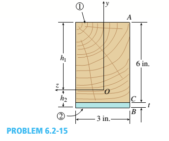
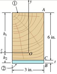
-15 A composite beam is constructed froma wood beam (3 in. x 6 in.) and a steel plate (3 in, wide). The wood and the steel are securely fastened to act as a single beam. The beam is subjected to a positive bending moment M. = 75 kip-in. Calculate the required thickness of the steel plate based on the following limit states:
- Allowable compressive stress in the wood = 2 ksi
- Allowable tensile stress in the wood = 2 ksi
- Allowable tensile stress in the steel plate = 16 ksi Assume that Ew= 1,500 ksi and es= 30,000 ksi.
a.
The thickness required for the steel plate.
Answer to Problem 6.2.15P
The thickness required for the steel plate
Explanation of Solution
Given:
The given figure

The wooden beam of 3in.*6in. and steel plate with wide 3in. forms the beam. The positive bending moment is given as
Concept Used:
Normal stress that is maximum for steel,
Where,
Calculation:
Neutral axis location at the lower end is given as,
Substituting the values we have,
From the top the neutral axis distance is given as,
The wooden section moment of inertia is given as,
The steel section moment of inertia is given as,
The normal stress that is maximum in the section of steel,
Conclusion:
Thus, the thickness required for the steel plate is calculated by equating bending movement, wood inertia, steel inertia, steel inertia, wood modulus elasticity, steel modulus elasticity and height.
b.
The thickness required for the steel plate.
Answer to Problem 6.2.15P
The thickness required for the steel plate
Explanation of Solution
Given:
The given figure:

The wooden beam of 3in.*6in. and steel plate with wide 3in. forms the beam. The positive bending moment is given as
Concept Used:
Wood maximum stress of top part is given as,
Where,
Calculation:
Normal Maximum stress for Wood at the top,
Substituting the values we have,
Conclusion:
Thus, the thickness required for the steel plate is calculated by wood modulus elasticity, steel modulus elasticity and height.
c.
The thickness required for the steel plate.
Answer to Problem 6.2.15P
Explanation of Solution
Given:
The given figure:
The wooden beam of 3in.*6in. and steel plate with wide 3in. forms the beam. The positive bending moment is given as
Concept Used:
Wood maximum stress of bottom part is given as,,
Where,
Calculation:
Maximum stress Maximum for Wood at the bottom,
Substituting the values we have,
Conclusion:
Thus, the thickness required for the steel plate is calculated by maximum stress, steel inertia moment, wood inertia moment , wood modulus elasticity, steel modulus elasticity.
Want to see more full solutions like this?
Chapter 6 Solutions
Mechanics of Materials (MindTap Course List)


- A square tube section has side dimension of 20 in. arid thickness of 0.5 in. If the section is used for a 10-ft-long beam subjected to 1250 kip-in, torque at both ends, calculate the maximum shear stress and the angle of twist between the ends. Use G = 11,600 ksi.arrow_forwardA two-axle carriage that is part of an over head traveling crane in a testing laboratory moves slowly across a simple beam AB (sec figure). The load transmitted to the beam from the front axle is 2200 lb and from the rear axle is 3800 lb. The weight of the beam itself may be disregarded. Determine the minimum required section modulus S for the beam if the allowable bending stress is 17,0 ksi, the length of the beam is 18 ft, and the wheelbase of the carriage is 5 ft. Select the most economical I-beam (S shape) from Table F-2(a), Appendix F.arrow_forwardTwo wood beams, each of rectangular cross section (3.0 in. x 4.0 in., actual dimensions), are glued together to form a solid beam with dimensions 6.0 in. x 4.0 in. (sec figure). The beam is simply supported with a span of S ft. What is the maximum moment Mmaxthat may be applied at the left support if the allowable shear stress in the glued joint is 200 psi? (Include the effects of the beams own weight, assuming that the wood weighs 35 lb/ft3.) Repeat part (a) if Mmaxis based on allowable bending stress of 2500 psi.arrow_forward
- The wood joists supporting a plank Floor (see figure) are 38 mm × 220 mm in cross section (actual dimensions) and have a span length of L = 4.0 m. The floor load is 5.0 kPa, which includes the weight of the joists and the floor. (a) Calculate the maximum permissible spacing s of the joists if the allowable bending stress is 14 M Pa. (Assume that each joist may be represented as a simple beam carrying a uniform load.) (b) If spacing s = 406 mm, what is the required depth ft of the joist? Assume all other variables remain unchanged.arrow_forwardA cantilever beam of length L = 2 m supports a load P = 8,0 kN (sec figure). The beam is made of wood with cross-sectional dimensions 120 mm x 200 mm. Calculate the shear stresses due to the load/"at points located 25 mm, 50 mm, 75 mm, and 100 mm from the top surface of the beam. From these results, plot a graph showing the distribution of shear stresses from top to bottom of the beam.arrow_forwardA weight W = 20 kN falls through a height h = 1,0 mm onto the midpoint or a simple beam of length L = 3 m (see figure). The beam is made of wood with square cross section (dimension don each side) and E = 12 GPa. If the allowable bending stress in the wood is °aLLow =10MPa, what is the minimum required dimensionarrow_forward
- A floor system in a small building consists of wood planks supported by 2-in. (nominal width) joists spaced at distance s and measured from center to center (see figure). The span length L of each joist is 12 ft, the spacing s of the joists is 16 in., and the allowable bending stress in the wood is 1250 psi. The uniform floor load is 120 lb/ft", which includes an allowance for the weight of the floor system itself. Calculate the required section modulus S for the joists, and then select a suitable joist size (surfaced lumber) from Appendix G, assuming that each joist may be represented as a simple beam carrying a uniform load. What is the maximum floor load that can be applied to your final beam selection in part (a)?arrow_forwardA heavy object of weight W is dropped onto the midpoint of a simple beam AB from a height h (see figure). Obtain a formula for the maximum bending stress ^ma* due to tne filing weight in terms of h, st, and 5st, where it is the maximum bending stress and Sstis the deflection at the midpoint when the weight W acts on the beam as a statically applied load. Plot a graph of the ratio o"max/ö"it (that is, the ratio of the dynamic stress to the static stress) versus the ratio iifS^r(Let h/S^ vary from 0 to 10.)arrow_forward-1 through 5.10-6 A wide-flange beam (see figure) is subjected to a shear force V. Using the dimensions of the cross section, calculate the moment of inertia and then determine the following quantities: The maximum shear stress tinixin the web. The minimum shear stress rmin in the web. The average shear stress raver (obtained by dividing the shear force by the area of the web) and the ratio i^/t^ The shear force carried in the web and the ratio V^tV. Note: Disregard the fillets at the junctions of the web and flanges and determine all quantities, including the moment of inertia, by considering the cross section to consist of three rectangles. 5.10-5 Wide-flange shape, W 18 x 71 (sec Table F-l, Appendix F); V = 21 k.arrow_forward
- A singly symmetric beam with a T-section (see figure) has cross-sectional dimensions b = 140 mm, a = 190, 8 mm, b. = 6,99 mm, and fc = 11,2 mm. Calculate the plastic modulus Z and the shape factor.arrow_forwardA box beam is constructed of four wood boards as shown in the figure part a. The webs are S in, x 1 irt and the flanges arc 6 in. X 1 in. boards (actual dimensions), joined by screws for which the allowable load in shear is F = 250 lb per screw. Calculate the maximum permissible longitudinal spacing ,vfflax of the screws if the shear force ^is 12001b. Repeat part (a) if the flanges arc attached to the webs using a horizontal arrangement of screws as shown in the figure part b.arrow_forward-6 Calculate the maximum deflection of a uniformly loaded simple beam if the span length L = 2.0 m, the intensity of the uniform load q = 2.0 kN/m, and the maximum bending stress = 60 MPa, The cross section of the beam is square, and the material is aluminum having modulus of elasticity E = 70 GPa. (Use the formulas of Example 9-1.)arrow_forward
 Mechanics of Materials (MindTap Course List)Mechanical EngineeringISBN:9781337093347Author:Barry J. Goodno, James M. GerePublisher:Cengage Learning