
Concept explainers
Videos
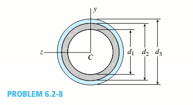
A plastic-lined steel pipe has the cross-sectional shape shown in the figure. The steel pipe has an outer diameter d1= 100 mm and an inner diameter d2= 94 mm. The plastic liner has an inner diameter d1= 82 mm. The modulus of elasticity of the steel is 75 times the modulus of the plastic.
- Determine the allowable bending moment Mallowif the allowable stress in the steel is 35 M Pa and in the plastic is 600 kPa.
i.
The allowable bending moment if the allowable stress for steel is 35 MPa and plastic 600 Kpa
Answer to Problem 6.2.8P
Allowable bending moment for plastic, Mallowableplastic = 1050.8 N-m
Allowable bending moment for Copper, Mallowablesteel =768.25 N-m
Explanation of Solution
Given:
Allowable stress for steel, ssteel = 35 MPa
Allowable stress for plastic, splastic= 600 kPa
d1= 82 mm
d2= 94 mm
d3= 100 mm
Esteel= 75*Eplastic
Concept Used:
Calculation:
Conclusion:
Allowable bending moment for plastic, Mallowableplastic = 1050.8 N-m
Allowable bending moment for Copper, Mallowablesteel =768.25 N-m
ii.
The value of the diameter of the copper rod for a balanced design
Answer to Problem 6.2.8P
The maximum moment is 1050.76 N-m in balanced condition
Explanation of Solution
Given:
Allowable stress for titanium, sti = 840 MPa
Allowable stress for titanium, scu= 700 MPa
Outer Diameter of the titanium rod, d2 = 40 mm
Eti= 110 GPa
Ecu= 120 GPa
Concept Used:
Calculation:
Conclusion:
The maximum moment is 1050.76 N-m in balanced condition
Want to see more full solutions like this?
Chapter 6 Solutions
Mechanics of Materials (MindTap Course List)


- A wood beam reinforced by an aluminum channel section is shown in the figure. The beam has a cross section of dimensions 150 mm x 250 mm, and the channel has a uniform thickness of 6.5 mm. If the allowable stresses in the wood and aluminum are 8 M Pa and 38 M Pa, respectively, and if their moduli of elasticity are in the ratio 1 to 6, what is the maximum allowable bending moment for the beam?arrow_forwardA thin-walled aluminum tube of rectangular cross section (sec fig me) has a centerline dimensions b = 6.0 in. and b = 4.0 in. The wall thickness t is constant and equal to 0.25 in. Determine the shear stress in the tube due to a torque T = 15 kip-in. Determine the angle of twist (in degrees) if the length L of the tube is 50 in. and the shear modulus G is 4.0 x 10⁶ psi.arrow_forwardThe beam ABC shown in the figure is simply supported at A and B and has an overhang from B to C. The loads consist of a horizontal force P1= 4,0 kN acting at the end of a vertical arm and a vertical force P2= 8.0 kN acting at the end of the overhang, Determine the shear force Fand bending moment M at a cross section located 3,0 m from the left-hand support. Note: Disregard the widths of the beam and vertical arm and use centerline dimensions when making calculations, Find the value of load A that results in V = 0 at a cross section located 2.0 m from the left-hand support. If P2= 8.0 kN, find the value of load P1that results in M = 0 at a cross section located 2,0 m from the left-hand support.arrow_forward
- A thin-walled rectangular tube has uniform thickness t and dimensions a x b to the median line of the cross section (see figure). How does the shear stress in the tube vary with the ratio = a/b if the total length Lmof the median line of the cross section and the torque T remain constant? From your results, show that the shear stress is smallest when the tube is square (ß = 1).arrow_forwardThe cross section of a composite beam made of aluminum and steel is shown in the figure. The moduli of elasticity are TA= 75 GPa and Es= 200 GPa. Under the action of a bending moment that produces a maximum stress of 50 M Pa in the aluminum, what is the maximum stress xs in the steel? If the height of the beam remains at 120 mm and allowable stresses in steel and aluminum are defined as 94 M Pa and 40 M Pa, respectively, what heights h and h. arc required for aluminum and steel, respectively, so that both steel and aluminum reach their allowable stress values under the maximum moment?arrow_forwardA thin-walled steel tube of rectangular cross section (see figure) has centerline dimensions b = 150 mm and h = 100 mm. The wall thickness t is constant and equal to 6.0 mm. Determine the shear stress in the tube due to a torque T = 1650 N · m. Determine the angle of twist (in degrees) if the length L of the tube is 1.2 m and the shear modulus G is 75 GPa.arrow_forward
- Consider the preceding problem if the beam has width h = 15 mm, the aluminum strips have thickness t = 3 mm, the plastic segments have heights d = 40 mm and 3 tf = 120 mm, and the total height of the beam is h = 212 mm. Also, the moduli of elasticity are EA= 75 GPa and Ep=3 GPa, respectively. Determine the maximum stresses o., and o\, in the aluminum and plastic, respectively, due to a bending moment of 1.0 kN - m.arrow_forwardA solid circular bar having diameter d is to be replaced by a rectangular tube having cross-sectional dimensions d × 2d to the median line of the cross section (see figure). Determine the required thickness tminof the tube so that the maximum shear stress in the tube will not exceed the maximum shear stress in the solid bar.arrow_forwardDerive the following formula for the distance e from the centerline of the wall to the shear center S for the hat section of constant thickness shown in the figure: Also, check the formula for the special case of a channel section (a = 0).arrow_forward
- A U-shaped cross section of constant thickness is shown in the figure. Derive the following formula for the distance e from the center of the semicircle to the shear center. Also, plot a graph showing how the distance e (expressed as the non dimensional ratio e/r varies as a function of the ratio b/r. (Let b/r range from 0 to 2.)arrow_forwardThe cross section of a slit circular tube of constant thickness is shown in the figure, Show that the distance e from the center of the circle to the shear center S is equal to 2r in the figure part a. Find an expression for e if flanges with the same thickness as that of the tube arc added, as shown in the figure part b.arrow_forwardThe cross section of a sand wie h beam consisting of aluminum alloy faces and a foam core is shown in the figure. The width b of the beam is 8.0 in, the thickness I of the faces is 0.25 in., and the height hcof the core is 5.5 in. (total height h = 6.0 in). The moduli of elasticity are 10.5 × 10⁶ psi for the aluminum faces and 12.000 psi for the foam core. A bending moment M = 40 kip-in. acts about the z axis. Determine the maximum stresses in the faces and the core using (a) the general theory for composite beams and (b) the approximate theory for sandwich beams.arrow_forward
 Mechanics of Materials (MindTap Course List)Mechanical EngineeringISBN:9781337093347Author:Barry J. Goodno, James M. GerePublisher:Cengage Learning