
Concept explainers
Videos
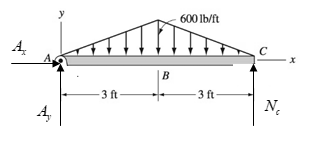
For the beam shown, derive the expressions for V and M, and draw the shear force and bending moment diagrams. Neglect the weight of the beam.
Derive equation for
Answer to Problem 6.31P
The equation for
Explanation of Solution
Draw the Free body diagram for the beam as shown below.
Write the expression for the equilibrium of forces in
Here,
Take the summation of all the forces in
Simplify the above expression.
Here,
Take moment about point
Substitute
Substitute
Simplify the above for
Take section
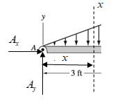
From the above diagram, by the property of similar triangles magnitude of UVL at distance
Simplify the above expression for
Here,
Take shear force on left side of the section
Here,
Substitute
Take moment about section
Here,
Substitute
Take section
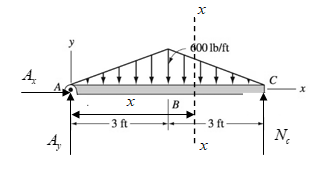
From the above diagram, by the property of similar triangles magnitude of UVL at distance
Simplify the above expression for
Take shear force on left side of the section
Here,
Substitute
Take moment about section
Substitute
Simplify the above expression.
Thus, from equation (2) and (4) the equation for
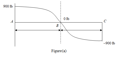
Draw the shear force diagram for the beam as shown below.
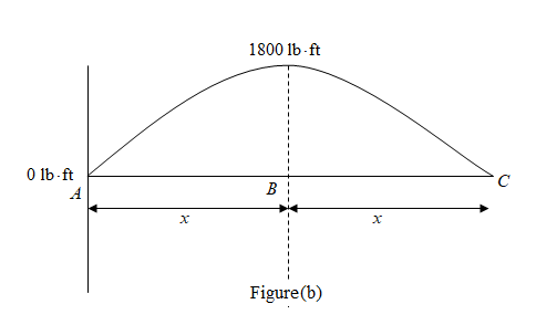
Draw the Bending moment diagram for the beam as shown below.
Want to see more full solutions like this?
Chapter 6 Solutions
International Edition---engineering Mechanics: Statics, 4th Edition


 International Edition---engineering Mechanics: St...Mechanical EngineeringISBN:9781305501607Author:Andrew Pytel And Jaan KiusalaasPublisher:CENGAGE L