
Mechanics of Materials (MindTap Course List)
9th Edition
ISBN: 9781337093347
Author: Barry J. Goodno, James M. Gere
Publisher: Cengage Learning
expand_more
expand_more
format_list_bulleted
Videos
Textbook Question
Chapter 6, Problem 6.3.7P
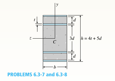
The cross section of a beam made of thin strips of aluminum separated by a lightweight plastic is shown in the figure. The beam has width b = 3.0 in., the aluminum strips have thickness t = 0.1 in., and the plastic segments have heights d = 1.2 in. and 3d = 3.6 in. The total height of the beam is h = 6.4 in.
The moduli of elasticity for the aluminum and plastic are EM= 11 X 106 psi and Ep= 440 X 10* psi, respectively.
Determine the maximum stresses trAiand
Expert Solution & Answer

Trending nowThis is a popular solution!

Chapter 6 Solutions
Mechanics of Materials (MindTap Course List)
Ch. 6 - A composite beam is constructed using a steel...Ch. 6 - A wood beam is strengthened using two steel plates...Ch. 6 - A composite beam consisting of fiberglass faces...Ch. 6 - A wood beam with cross-sectional dimensions 200 mm...Ch. 6 - A hollow box beam is constructed with webs of...Ch. 6 - A r o lukI f/frm f «m t ub e of ou t sid e d ia...Ch. 6 - A beam with a guided support and 10-ft span...Ch. 6 - A plastic-lined steel pipe has the cross-sectional...Ch. 6 - The cross section of a sand wie h beam consisting...Ch. 6 - The cross section of a sandwich beam consisting of...
Ch. 6 - A bimetallic beam used in a temperature-control...Ch. 6 - A simply supported composite beam 3 m long carries...Ch. 6 - A simply supported wooden I-beam with a 12-ft span...Ch. 6 - -14 A simply supported composite beam with a 3.6 m...Ch. 6 - -15 A composite beam is constructed froma wood...Ch. 6 - A wood beam in a historic theater is reinforced...Ch. 6 - Repeat Problem 6.2-1 but now assume that the steel...Ch. 6 - Repeat Problem 6.2-17 but now use a...Ch. 6 - A sandwich beam having steel faces enclosing a...Ch. 6 - A wood beam 8 in. wide and 12 in. deep (nominal...Ch. 6 - A simple beam of span length 3.2 m carries a...Ch. 6 - A simple beam that is 18 ft long supports a...Ch. 6 - The composite beam shown in the figure is simply...Ch. 6 - The cross section of a beam made of thin strips of...Ch. 6 - Consider the preceding problem if the beam has...Ch. 6 - A simple beam thai is IS ft long supports a...Ch. 6 - The cross section of a composite beam made of...Ch. 6 - A beam is constructed of two angle sections, each...Ch. 6 - The cross section of a bimetallic strip is shown...Ch. 6 - A W 12 x 50 steel wide-flange beam and a segment...Ch. 6 - A reinforced concrete beam (see figure) is acted...Ch. 6 - A reinforced concrete T-beam (see figure) is acted...Ch. 6 - A reinforced concrete slab (see figure) is...Ch. 6 - A wood beam reinforced using two channels is...Ch. 6 - A wood beam reinforced by an aluminum channel...Ch. 6 - A beam with a rectangular cross section supports...Ch. 6 - A wood beam with a rectangular cross section (see...Ch. 6 - Solve the preceding problem for the following...Ch. 6 - A simply supported wide-flange beam of span length...Ch. 6 - Solve the preceding problem using the fol...Ch. 6 - A wood cantilever beam with a rectangular cross...Ch. 6 - Solve the preceding problem for a cantilever beam...Ch. 6 - A 2-m-long cantilever beam is constructed using a...Ch. 6 - A wood beam AB with a rectangular cross section (4...Ch. 6 - A steel beam of I-section (see figure) is simply...Ch. 6 - A cantilever beam with a wide-flange cross section...Ch. 6 - Solve the preceding problem using a W 310 x 129...Ch. 6 - A cantilever beam of W 12 × 14 section and length...Ch. 6 - A cantilever beam built up from two channel...Ch. 6 - A built-Lip I-section steel beam with channels...Ch. 6 - Repeat Problem 6.4-14 but use the configuration of...Ch. 6 - A beam with a channel section is subjected to a...Ch. 6 - A beam with a channel section is subjected to a...Ch. 6 - An angle section with equal legs is subjected to a...Ch. 6 - An angle section with equal legs is subjected to a...Ch. 6 - A beam made up all woun equal leg angles is...Ch. 6 - The Z-section of Example D-7 is subjected to M = 5...Ch. 6 - The cross section of a steel beam is constructed...Ch. 6 - The cross section of a steel beam is shown in the...Ch. 6 - A beam with a semicircular cross section of radius...Ch. 6 - .10 A built-up bourn supporting a condominium...Ch. 6 - Asteelpost (E = 30 × 106 psi) having thickness t =...Ch. 6 - A C 200 x 17.1 channel section has an angle with...Ch. 6 - A cold-formed steel section is made by folding a...Ch. 6 - A simple beam with a W 10 x 30 wide-flange cross...Ch. 6 - Solve the preceding problem for a W 250 × 44.8...Ch. 6 - A beam of wide-flange shape, W 8 x 28, has the...Ch. 6 - Solve the preceding problem for a W 200 × 41,7...Ch. 6 - Calculate the distance e from the cent crime of...Ch. 6 - Calculate the distance e from the centerline of...Ch. 6 - The cross section of an unbalanced wide-flange...Ch. 6 - The cross section of an unbalanced wide-flange...Ch. 6 - The cross section of a channel beam with double...Ch. 6 - The cross section of a slit circular tube of...Ch. 6 - The cross section of a slit square tube of...Ch. 6 - The cross section of a slit rectangular tube of...Ch. 6 - A U-shaped cross section of constant thickness is...Ch. 6 - Derive the following formula for the distance e...Ch. 6 - Derive the following formula for the distance e...Ch. 6 - The cross section of a sign post of constant...Ch. 6 - A cross section in the shape of a circular arc of...Ch. 6 - Determine the shape factor f for a cross section...Ch. 6 - (a) Determine the shape factor/for a hollow...Ch. 6 - A propped cantilever beam of length L = 54 in....Ch. 6 - A steel beam of rectangular cross section is 40 mm...Ch. 6 - .5 Calculate the shape factor j for the...Ch. 6 - Solve the preceding problem for a wide-flange beam...Ch. 6 - Determine the plastic modulus Z and shape...Ch. 6 - Prob. 6.10.8PCh. 6 - Prob. 6.10.9PCh. 6 - Prob. 6.10.10PCh. 6 - A hollow box beam with height h = 16 in,, width h...Ch. 6 - Solve the preceding problem for a box beam with...Ch. 6 - A hollow box beam with height h = 9.5 in., inside...Ch. 6 - Solve the preceding problem for a box beam with...Ch. 6 - The hollow box beam shown in the figure is...Ch. 6 - Prob. 6.10.16PCh. 6 - Prob. 6.10.17PCh. 6 - A singly symmetric beam with a T-section (see...Ch. 6 - A wide-flange beam with an unbalanced cross...Ch. 6 - .20 Determine the plastic moment Mpfor beam having...
Knowledge Booster


Learn more about
Need a deep-dive on the concept behind this application? Look no further. Learn more about this topic, mechanical-engineering and related others by exploring similar questions and additional content below.Similar questions
- A simple beam that is 18 ft long supports a uniform load of intensity q. The beam is constructed of two C8 x 11.5 sections (channel sections or C-shapes) on either side of a 4 × 8 (actual dimensions) wood beam (see the cross section shown in the figure part a). The modulus of elasticity of the steel (E; = 30,000 ksi) is 20 times that of the wood (Ew). (a) If the allowable stresses in the steel and wood are 12,000 psi and 900 psi, respectively, what is the allowable load qmax Note: Disregard the weight of the beam, and see Table F-3(a) of Appendix F for the dimensions and properties of the C-shape beam. (b) If the beam is rotated 90° to bend about its v axis (see figure part b) and uniform load q = 250 lb/ft is applied, find the maximum stresses trs and crw in the steel and wood, respectively Include the weight of the beam. (Assume weight densities of 35 lb/ft3 and 490 lb/ft3 for the wood and steel, respectively.)arrow_forwardThe cross section of a sand wie h beam consisting of aluminum alloy faces and a foam core is shown in the figure. The width b of the beam is 8.0 in, the thickness I of the faces is 0.25 in., and the height hcof the core is 5.5 in. (total height h = 6.0 in). The moduli of elasticity are 10.5 × 10⁶ psi for the aluminum faces and 12.000 psi for the foam core. A bending moment M = 40 kip-in. acts about the z axis. Determine the maximum stresses in the faces and the core using (a) the general theory for composite beams and (b) the approximate theory for sandwich beams.arrow_forwardA beam is constructed of two angle sections, each L5 x 3 x 1/2, that reinforce a 2 x g (actual dimensions) wood plank (see the cross section shown in the figure). The modulus of elasticity for the wood is £w = L2 X 106 psi and for the steel is Es= 30 x 106 psi. Find the allowable bending moment M3][cmfor the beam if the allowable stress in the wood is trv= 1100 psi and in the steel is 3 = 12,000 psi. Note: Disregard the weight of the beam, and see Table F-5(a) of Appendix F for the dimensions and properties of the angles.arrow_forward
- The cross section of a sandwich beam consisting of fiberglass faces and a lightweight plastic core is shown in the figure. The width b of the beam is 50 mm, the thickness I of the faces is 4 mm, and the height hcof the core is 92 mm (total height A = 100 mm). The moduli of elasticity are 75 GPa for the fiberglass and 1.2 GPa for the plastic. A bending moment M = 275 N · m acts about the z axis. Determine the maximum stresses in the faces and the core using (a) the general theory for composite beams and (b) the approximate theory for sandwich beams.arrow_forwardA W 12 x 50 steel wide-flange beam and a segment of a 4-inch thick concrete slab (see figure) jointly resist a positive bending moment of 95 kip-ft. The beam and slab are joined by shear connectors that are welded to the steel beam. (These connectors resist the horizontal shear at the contact surface.) The moduli of elasticity of the steel and the concrete are in the ratio 12 to 1. Determine the maximum stresses r1 and xtin the steel and concrete, respectively. Note: See Table F-l(a) of Appendix F for the dimensions and properties of the steel beam.arrow_forwardA beam of square cross section (a = length of each side) is bent in the plane of a diagonal (see figure). By removing a small amount of material at the top and bottom corners, as shown by the shaded triangles in the figure, you can increase the section modulus and obtain a stronger beam, even though the area of the cross section is reduced. Determine the ratio ß defining the areas that should be removed in order to obtain the strongest cross section in bending. By what percent is the section modulus increased when the areas arc removed?arrow_forward
- A beam of wide-flange shape, W 8 x 28, has the cross section shown in the figure. The dimensions are b = 6.54 in., h = 8.06 in., fw = 0.285 in., and tf = 0.465 in.. The loads on the beam produce a shear force V = 7.5 kips at the cross section under consideration. Use center line dimensions to calculate the maximum shear stress raiaxin the web of the beam. Use the more exact analysis of Section 5,10 in Chapter 5 to calculate the maximum shear stress in the web of the beam and compare it with the stress obtained in part .arrow_forwardA cantilever beam AB having rectangular cross sections with varying width bxand varying height hxis subjected to a uniform load of intensity q (sec figure). If the width varies linearly with x according to the equation hx= bBxiL^ how should the height hxvary as a function of v in order to have a fully stressed beam? (Express hxin terms of the height hBat the fixed end of the beam.)arrow_forwardThe cantilever beam AB shown in the figure is an S6 × 12.5 steel I-beam with E = 30 × 106 psi. The simple beam DE is a wood beam 4 in. x 12 in. (nominal dimensions) in cross section with E = 1.5 x 10⁶ psi. A steel rod AC of diameter 0.25 in., length 10 ft, and E = 30 x 106 psi serves as a hanger joining the two beams. The hanger fits snugly between the beams before the uniform load is applied to beam DE. Determine the tensile force Fin the hanger and the maximum bending moments MABand MDEin the two beams due to the uniform load, which has an intensity q = 400 lb/ft. Hint: To aid in obtaining the maximum bending moment in beam DE, draw the shear-force and bending-moment diagrams.arrow_forward
- A wood beam reinforced by an aluminum channel section is shown in the figure. The beam has a cross section of dimensions 150 mm x 250 mm, and the channel has a uniform thickness of 6.5 mm. If the allowable stresses in the wood and aluminum are 8 M Pa and 38 M Pa, respectively, and if their moduli of elasticity are in the ratio 1 to 6, what is the maximum allowable bending moment for the beam?arrow_forwardA hollow box beam is constructed with webs of Douglas-fir plywood and flanges of pine, as shown in the figure in a cross-sectional view. The plywood is 1 in. thick and 12 in. wide; the flanges are 2 in. × 4 in. (nominal size). The modulus of elasticity for the plywood is 1,800,000 psi and for the pine is 1,400,000 psi. If the allowable stresses are 2000 psi for the plywood and 1750 psi for the pine, find the allowable bending moment Mmaxwhen the beam is bent about the z axis. Repeat part (a) if the beam is now bent about its y-axis.arrow_forwardThe cross section of a composite beam made of aluminum and steel is shown in the figure. The moduli of elasticity are TA= 75 GPa and Es= 200 GPa. Under the action of a bending moment that produces a maximum stress of 50 M Pa in the aluminum, what is the maximum stress xs in the steel? If the height of the beam remains at 120 mm and allowable stresses in steel and aluminum are defined as 94 M Pa and 40 M Pa, respectively, what heights h and h. arc required for aluminum and steel, respectively, so that both steel and aluminum reach their allowable stress values under the maximum moment?arrow_forward
arrow_back_ios
SEE MORE QUESTIONS
arrow_forward_ios
Recommended textbooks for you
 Mechanics of Materials (MindTap Course List)Mechanical EngineeringISBN:9781337093347Author:Barry J. Goodno, James M. GerePublisher:Cengage Learning
Mechanics of Materials (MindTap Course List)
Mechanical Engineering
ISBN:9781337093347
Author:Barry J. Goodno, James M. Gere
Publisher:Cengage Learning
Mechanics of Materials Lecture: Beam Design; Author: UWMC Engineering;https://www.youtube.com/watch?v=-wVs5pvQPm4;License: Standard Youtube License