
Mechanics of Materials (MindTap Course List)
9th Edition
ISBN: 9781337093347
Author: Barry J. Goodno, James M. Gere
Publisher: Cengage Learning
expand_more
expand_more
format_list_bulleted
Concept explainers
Videos
Textbook Question
Chapter 6, Problem 6.5.10P
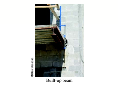
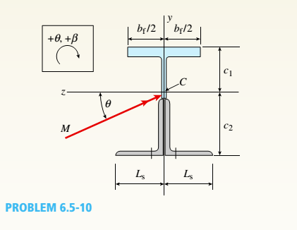
.10 A built-up bourn supporting a condominium balcony is made up of a structural T (one half of a W 200 x 31.3) for the top flange and web and two angles (2 L 2 / b / 6.4. long legal back-lo-backl lot the bottom flange and web. as shown. The beam is subjected to a bending moment .1/ having its
Determine the or ion ta I ion of the neutral axis and calculate the maximum tensile stress ir, and maximum compressive stress tr. in ".he beam. .Assume that 9 = 30°andM = 15 kN · m.
Use the numerical properties: c =4.111mm, c2 =4.169 mm, of = 134 mm, I, = 76 mm, A = 4144 mm 3 =3.88 X 106 mm 4, and = 34.18 X 10 mm 4.
Expert Solution & Answer
Want to see the full answer?
Check out a sample textbook solution
Students have asked these similar questions
A beam having a tee-shaped cross section is subjected to equal 13 kN-m bending moments, as shown. Assume bf = 95 mm, tf = 25 mm, d = 165 mm, tw = 40 mm. The cross-sectional dimensions of the beam are also shown. Determine(a) the centroid location (measured upward from the bottom), the moment of inertia about the z axis, and the controlling section modulus about the z axis.(b) the bending stress at point H (positive if tensile and negative if compressive).(c) the maximum bending stress (positive if tensile and negative if compressive) produced in the cross section.
A simply supported beam AB = 10 m has a hollow rectangular cross-section with 17 cm as width, 28 cm as depth and inner thickness as 2 cm is subjected to a point load of 7 N & 5 N acting at C and D respectively and a uniformly distributed load (UDL) of 8 N/m starts from mid-span and ends at the right support of the beam. Determine the maximum bending stress and the bending stress at 2 cm from the top. Take AC = 2 m & CD = 2 m.
note ; Please solve number 3.4.5.6.7
i) Reaction force at B = 33.4N
ii) Reaction Force at A = 18.6N
iii) The distance from B at which the shear Force value changes from "-" to "+" =
iv) Maximum Bending Moment (Please write the Maximum bending moment valve in "Nm") =
v) Moment of Inertia, I =
vi) Maximum bending stress =
vii) Bending stress at 2 cm from the top =
A simply supported beam AB = 9 m has a hollow rectangular cross-section with 13 cm as width, 20 cm as depth and inner thickness as 1 cm is subjected to a point load of 8 N & 8 N acting at C and D respectively and a uniformly distributed load (UDL) of 9 N/m starts from mid-span and ends at the right support of the beam. Determine the maximum bending stress and the bending stress at 1 cm from the top. Take AC = 1 m & CD = 2 m.
note sole 4.5.6.and 7
i) Reaction force at B in (N)=
ii) Reaction Force at A in(N)=
iii) The distance from B at which the shear Force value changes from "-" to "+" in (m)=
iv) Maximum Bending Moment (Please write the Maximum bending moment valve in "Nm") =
v) Moment of Inertia, I in (m^4)=
vi) Maximum bending stress in (N/m^2)=
vii) Bending stress at 1 cm from the top in (N/m^2) =
Chapter 6 Solutions
Mechanics of Materials (MindTap Course List)
Ch. 6 - A composite beam is constructed using a steel...Ch. 6 - A wood beam is strengthened using two steel plates...Ch. 6 - A composite beam consisting of fiberglass faces...Ch. 6 - A wood beam with cross-sectional dimensions 200 mm...Ch. 6 - A hollow box beam is constructed with webs of...Ch. 6 - A r o lukI f/frm f «m t ub e of ou t sid e d ia...Ch. 6 - A beam with a guided support and 10-ft span...Ch. 6 - A plastic-lined steel pipe has the cross-sectional...Ch. 6 - The cross section of a sand wie h beam consisting...Ch. 6 - The cross section of a sandwich beam consisting of...
Ch. 6 - A bimetallic beam used in a temperature-control...Ch. 6 - A simply supported composite beam 3 m long carries...Ch. 6 - A simply supported wooden I-beam with a 12-ft span...Ch. 6 - -14 A simply supported composite beam with a 3.6 m...Ch. 6 - -15 A composite beam is constructed froma wood...Ch. 6 - A wood beam in a historic theater is reinforced...Ch. 6 - Repeat Problem 6.2-1 but now assume that the steel...Ch. 6 - Repeat Problem 6.2-17 but now use a...Ch. 6 - A sandwich beam having steel faces enclosing a...Ch. 6 - A wood beam 8 in. wide and 12 in. deep (nominal...Ch. 6 - A simple beam of span length 3.2 m carries a...Ch. 6 - A simple beam that is 18 ft long supports a...Ch. 6 - The composite beam shown in the figure is simply...Ch. 6 - The cross section of a beam made of thin strips of...Ch. 6 - Consider the preceding problem if the beam has...Ch. 6 - A simple beam thai is IS ft long supports a...Ch. 6 - The cross section of a composite beam made of...Ch. 6 - A beam is constructed of two angle sections, each...Ch. 6 - The cross section of a bimetallic strip is shown...Ch. 6 - A W 12 x 50 steel wide-flange beam and a segment...Ch. 6 - A reinforced concrete beam (see figure) is acted...Ch. 6 - A reinforced concrete T-beam (see figure) is acted...Ch. 6 - A reinforced concrete slab (see figure) is...Ch. 6 - A wood beam reinforced using two channels is...Ch. 6 - A wood beam reinforced by an aluminum channel...Ch. 6 - A beam with a rectangular cross section supports...Ch. 6 - A wood beam with a rectangular cross section (see...Ch. 6 - Solve the preceding problem for the following...Ch. 6 - A simply supported wide-flange beam of span length...Ch. 6 - Solve the preceding problem using the fol...Ch. 6 - A wood cantilever beam with a rectangular cross...Ch. 6 - Solve the preceding problem for a cantilever beam...Ch. 6 - A 2-m-long cantilever beam is constructed using a...Ch. 6 - A wood beam AB with a rectangular cross section (4...Ch. 6 - A steel beam of I-section (see figure) is simply...Ch. 6 - A cantilever beam with a wide-flange cross section...Ch. 6 - Solve the preceding problem using a W 310 x 129...Ch. 6 - A cantilever beam of W 12 × 14 section and length...Ch. 6 - A cantilever beam built up from two channel...Ch. 6 - A built-Lip I-section steel beam with channels...Ch. 6 - Repeat Problem 6.4-14 but use the configuration of...Ch. 6 - A beam with a channel section is subjected to a...Ch. 6 - A beam with a channel section is subjected to a...Ch. 6 - An angle section with equal legs is subjected to a...Ch. 6 - An angle section with equal legs is subjected to a...Ch. 6 - A beam made up all woun equal leg angles is...Ch. 6 - The Z-section of Example D-7 is subjected to M = 5...Ch. 6 - The cross section of a steel beam is constructed...Ch. 6 - The cross section of a steel beam is shown in the...Ch. 6 - A beam with a semicircular cross section of radius...Ch. 6 - .10 A built-up bourn supporting a condominium...Ch. 6 - Asteelpost (E = 30 × 106 psi) having thickness t =...Ch. 6 - A C 200 x 17.1 channel section has an angle with...Ch. 6 - A cold-formed steel section is made by folding a...Ch. 6 - A simple beam with a W 10 x 30 wide-flange cross...Ch. 6 - Solve the preceding problem for a W 250 × 44.8...Ch. 6 - A beam of wide-flange shape, W 8 x 28, has the...Ch. 6 - Solve the preceding problem for a W 200 × 41,7...Ch. 6 - Calculate the distance e from the cent crime of...Ch. 6 - Calculate the distance e from the centerline of...Ch. 6 - The cross section of an unbalanced wide-flange...Ch. 6 - The cross section of an unbalanced wide-flange...Ch. 6 - The cross section of a channel beam with double...Ch. 6 - The cross section of a slit circular tube of...Ch. 6 - The cross section of a slit square tube of...Ch. 6 - The cross section of a slit rectangular tube of...Ch. 6 - A U-shaped cross section of constant thickness is...Ch. 6 - Derive the following formula for the distance e...Ch. 6 - Derive the following formula for the distance e...Ch. 6 - The cross section of a sign post of constant...Ch. 6 - A cross section in the shape of a circular arc of...Ch. 6 - Determine the shape factor f for a cross section...Ch. 6 - (a) Determine the shape factor/for a hollow...Ch. 6 - A propped cantilever beam of length L = 54 in....Ch. 6 - A steel beam of rectangular cross section is 40 mm...Ch. 6 - .5 Calculate the shape factor j for the...Ch. 6 - Solve the preceding problem for a wide-flange beam...Ch. 6 - Determine the plastic modulus Z and shape...Ch. 6 - Prob. 6.10.8PCh. 6 - Prob. 6.10.9PCh. 6 - Prob. 6.10.10PCh. 6 - A hollow box beam with height h = 16 in,, width h...Ch. 6 - Solve the preceding problem for a box beam with...Ch. 6 - A hollow box beam with height h = 9.5 in., inside...Ch. 6 - Solve the preceding problem for a box beam with...Ch. 6 - The hollow box beam shown in the figure is...Ch. 6 - Prob. 6.10.16PCh. 6 - Prob. 6.10.17PCh. 6 - A singly symmetric beam with a T-section (see...Ch. 6 - A wide-flange beam with an unbalanced cross...Ch. 6 - .20 Determine the plastic moment Mpfor beam having...
Knowledge Booster


Learn more about
Need a deep-dive on the concept behind this application? Look no further. Learn more about this topic, mechanical-engineering and related others by exploring similar questions and additional content below.Similar questions
- .20 Determine the plastic moment Mpfor beam having the cross section shown in the figure ey=210 MPa.arrow_forwardA weight W = 4000 lb falls through a height h = 0.5 in, onto the midpoint of a simple beam of length L = 10 ft (see figure). Assuming that the allowable bending stress in the beam is = 18,000 psi and E = 30 x 10* psi, select the lightest wide-flange beam listed in Table F-l(a) in Appendix F that will be satisfactory.arrow_forwardThe cross section of an unbalanced wide-flange beam is shown in the figure. Derive the following formula for the distance /h from the centerline of one flange to the shear center S: h1t2b23ht1b13+t2b23 Also, check the formula for the special cases of a T-beam (b2= t2=0) and a balanced wide-flange beam (t2= ttand b2= ty).arrow_forward
- A tapered cantilever beam AB supports a concentrated load P at the free end (see figure). The cross sections of the beam are rectangular tubes with constant width b, outer Tube depth dAat A, and outer tube depth dB— ldA/2 at support B. The tube thickness is constant, as t = dA/20. IAis the moment of inertia of the outer tube at end A of the beam. If the moment of inertia of the tube is approximated as la{x) as defined, find the equation of the deflection curve and the deflection 5^ at the free end of the beam due to the load P.arrow_forwardThe hollow box beam shown in the figure is subjected to a bending moment M of such magnitude that the flanges yield but the webs remain linearly elastic. (a) Calculate the magnitude of the moment M if the dimensions of the cross section are A = 15 in., A] = 12.75 in., h = 9 in., and ey =7.5 in. Also, the yield stress is eY = 33 ksi. (b) What percent of the moment M is produced by the elastic core?arrow_forwardA simple beam ACE is constructed with square cross sections and a double taper (see figure). The depth of the beam at the supports is dAand at the midpoint is dc= 2d 4. Each half of the beam has length L. Thus, the depth and moment of inertia / at distance x from the left-hand end are, respectively, in which IAis the moment of inertia at end A of the beam. (These equations are valid for .x between 0 and L, that is, for the left-hand half of the beam.) Obtain equations for the slope and deflection of the left-hand half of the beam due to the uniform load. From the equations in part (a), obtain formulas for the angle of rotation 94at support A and the deflection Scat the midpoint.arrow_forward
- A simple beam with a W 10 x 30 wide-flange cross section supports a uniform load of intensity q = 3.0 kips/ft on a span of length L = 12 ft (sec figure). The dimensions of the cross section are q = 10.5 in., b = 5.81 in., t1= 0.510 in., and fw = 0.300 in. Calculate the maximum shear stress tjuly on cross section A—A located at distance d = 2.5 ft from the end of the beam. Calculate the shear stress rat point Bon the cross section. Point B is located at a distance a = 1.5 in. from the edge of the lower flange.arrow_forwardA rectangular beam with semicircular notches, as shown in part b of the figure, has dimensions h = 120 mm and h1= 100 mm. The maximum allowable bending stress in the plastic beam is emix = 6 M Pa, and the bending moment is M = 150 N · m. Determine the minimum permissible width bminof the beam.arrow_forwardA rectangular beam with notches and a hole (see figure) has dimensions h = 5.5 in., h1= 5 in., and width b = 1.6 in. The beam is subjected to a bending moment M = 130 kip-in., and the maximum allowable bending stress in the material (steel) is emax = 42,000 psi. What is the smallest radius Rminthat should be used in the notches? What is the diameter dmixof the largest hole that should be drilled at the mid height of the beam?arrow_forward
- A hollow box beam with height h = 9.5 in., inside height/i, = 8.0 in., width? = 5,25 in., and inside width =4.5 in. is shown in the figure. Assuming that the beam is constructed of steel with yield stress ty= 42 ksi calculate the yield moment My, plastic moment MPand shape factor f.arrow_forwardA W 12 x 50 steel wide-flange beam and a segment of a 4-inch thick concrete slab (see figure) jointly resist a positive bending moment of 95 kip-ft. The beam and slab are joined by shear connectors that are welded to the steel beam. (These connectors resist the horizontal shear at the contact surface.) The moduli of elasticity of the steel and the concrete are in the ratio 12 to 1. Determine the maximum stresses r1 and xtin the steel and concrete, respectively. Note: See Table F-l(a) of Appendix F for the dimensions and properties of the steel beam.arrow_forwardA C 200 x 17.1 channel section has an angle with equal legs attached as shown; the angle serves as a lintel beam. The combined steel section is subjected to a bending moment M having its vector directed along the z axis, as shown in the figure. The cent roi d C of the combined section is located at distances xtand ycfrom the centroid (C1) of the channel alone. Principal axes yl and yvare also shown in the figure and properties Ix1,Iy1and 0pare given. Find the orientation of the neutral axis and calculate the maximum tensile stress exand maximum compressive stress if the angle is an L 76 x 76 x 6.4 section and M = 3.5 kN - m. Use the following properties for principal axes for the combined section:/^, = 18.49 X 10⁶ nrai4,/;| = 1.602 X 106 mm4, ep= 7.448*(CW),_r£ = 10.70 mm,andvf= 24.07 mm.arrow_forward
arrow_back_ios
SEE MORE QUESTIONS
arrow_forward_ios
Recommended textbooks for you
 Mechanics of Materials (MindTap Course List)Mechanical EngineeringISBN:9781337093347Author:Barry J. Goodno, James M. GerePublisher:Cengage Learning
Mechanics of Materials (MindTap Course List)
Mechanical Engineering
ISBN:9781337093347
Author:Barry J. Goodno, James M. Gere
Publisher:Cengage Learning
Everything About COMBINED LOADING in 10 Minutes! Mechanics of Materials; Author: Less Boring Lectures;https://www.youtube.com/watch?v=N-PlI900hSg;License: Standard youtube license