
Videos
In the circuit shown in Figure P6.51, determine the range in small−signal voltage gain
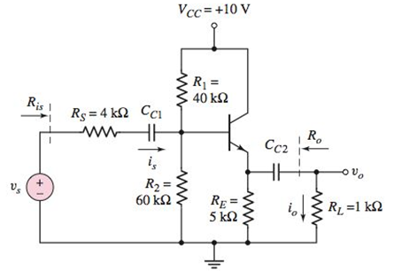
Figure P6.51
The range in small-signal voltage gain
Answer to Problem 6.51P
The final range of the voltage gain
The final range of the current gain
Explanation of Solution
Given:
Range of
The given circuit is:
From above circuit, considering BJT s single node, then by KCL, Quiescent emitter current
In CE mode,
Now, DC analysis of the given circuit:
Reduce source Vs to zero and open the capacitor as shown below:
The Theveninresistance is:
Modify the circuit as:
Therefore, Thevenin voltage from above circuit is
Modify the circuit as:
Applying KCL in the base-emitter loop to determine
From (3), (4) and (5) and
From equation (2) and
Now, small signal analysis of the given circuit:
Reduce dc voltage sources to zero, dc current source to open and capacitors to short.
Diffusion resistance
Input resistance and
The input resistance
Now, small signal current gain
From (3), (4) and (5) and
From equation (2) and
Diffusion resistance
Input resistance
The input resistance
Now, small signal current gain
The final range of the voltage gain
The final range of the current gain
Want to see more full solutions like this?
Chapter 6 Solutions
Microelectronics: Circuit Analysis and Design


- The capacitance of a capacitor can beaffected by dielectric material that,although not inside the capacitor, is nearenough to the capacitor to be polarized bythe fringing electric field that exists near acharged capacitor. This effect is usually ofthe order of picofarads (pF), but it can be used with appropriateelectronic circuitry to detect a change in the dielectric material sur-rounding the capacitor. Such a dielectric material might be thehuman body, and the effect described above might be used in thedesign of a burglar alarm. Consider the simplified circuit shown inFigure. . The voltage source has anf €= 1000 V, and tecapacitor has capacitance C = 10.0 pF. The electronic circuitryfor detecting the current, represented as an ammeter in the dia-gram, has negligible resistance and is capable of detecting a cur-rent that persists at a level of at least 1.00 μA for at least 200 μsafter the capacitance has changed abruptly from C to C’. The bur-glar alarm is designed to be activated if…arrow_forwardNote: (please write in detail Without plagiarism from the Internet) 5. Explain the phase difference between pure resistor, pure inductor and pure capacitor circuit in detail in an AC circuit.arrow_forwardA deemphasis circuit has a capacitor value of 0.02 µF. What value of resistor is needed? Give the closest stan- dard EIA value.arrow_forward
- In the compuntation of experimental time constant of an RC circuit in both the charging and discharging phase, explain the reason why we should not directly plot the capacitor voltage as a function of time in solving?arrow_forwardFind E at (0,0,5)m due to Q1=0.35uC at (0,4,0)m and Q2=-0.55uC at (3,0,0) m.arrow_forwardCell phones that use 4G technology receive signals broadcast between 2 GHz and 8 GHz. (a) If you want to create a simple L-R-C series circuit to detect a 4.0 GHz cell phone signal, what is the relevant value of the product LC, where L is the inductance and C is the capacitance? (b) If you choose a capacitor that has C = 1.0 * 10-15 F, what inductance do you need? (c) Suppose you want to wind your own toroidal inductor and fit it inside a box as thin as your cell phone. Based on the size of your phone, estimate the largest cross-sectional area possible for this. (d) Assume the largest allowable radius of the toroid is 1.0 cm and estimate the lowest number of windings needed to create your inductor, assuming the material inside has a relative permeability of 1.arrow_forward
- Sketch plots of the magnitudes of the impedances of a 10-mH inductance, a 10-μF capacitance, and a 50-Ω resistance to scale versus frequency for the range from zero to 1000 Hz.arrow_forwardIn the compuntation of experimental time constant of an RC circuit in the charging phase, explain the reason why we should not directly plot the capacitor voltage as a function of time in solving?arrow_forwardWhat is the ripple voltage (in Vrms) of a capacitor filter for a peak rectified voltage of 34 V, capacitor C = 561 µF, and a load current of 52 mA? No need to show your solution. Just write your numeric answer on the space provided. Round off your answer to 2 decimal places.arrow_forward
- Find the voltage across capacitor Vc(t) for time t>=0 Additionally, find the voltage across the 400ohm resistor for time t>=0arrow_forward16. 7.16 What percentage of the initial energy stored in the inductor in thecircuit is dissipated by the current-controlled voltagesource?arrow_forwardobtain the expression for Vo for the following circuurarrow_forward
 Introductory Circuit Analysis (13th Edition)Electrical EngineeringISBN:9780133923605Author:Robert L. BoylestadPublisher:PEARSON
 Delmar's Standard Textbook Of ElectricityElectrical EngineeringISBN:9781337900348Author:Stephen L. HermanPublisher:Cengage Learning
 Programmable Logic ControllersElectrical EngineeringISBN:9780073373843Author:Frank D. PetruzellaPublisher:McGraw-Hill Education
 Fundamentals of Electric CircuitsElectrical EngineeringISBN:9780078028229Author:Charles K Alexander, Matthew SadikuPublisher:McGraw-Hill Education
 Electric Circuits. (11th Edition)Electrical EngineeringISBN:9780134746968Author:James W. Nilsson, Susan RiedelPublisher:PEARSON
 Engineering ElectromagneticsElectrical EngineeringISBN:9780078028151Author:Hayt, William H. (william Hart), Jr, BUCK, John A.Publisher:Mcgraw-hill Education,