
Mechanics of Materials (MindTap Course List)
9th Edition
ISBN: 9781337093347
Author: Barry J. Goodno, James M. Gere
Publisher: Cengage Learning
expand_more
expand_more
format_list_bulleted
Concept explainers
Videos
Textbook Question
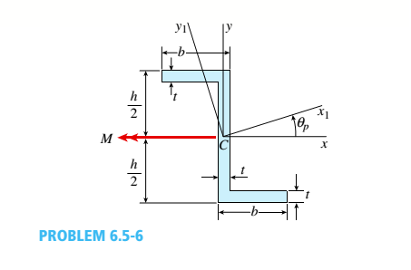
Chapter 6, Problem 6.5.6P
The Z-section of Example D-7 is subjected to M = 5 kN · m, as shown.
Determine the orientation of the neutral axis and calculate the maximum tensile stress c1and maximum compressive stress ocin the beam. Use the following numerical data: height; = 200 mm, width ft = 90 mm, constant thickness a = 15 mm, and B = 19.2e. Use = 32.6 × 106 mm4 and I2= 2.4 × 10e mm4 from Example D-7
Expert Solution & Answer

Trending nowThis is a popular solution!

Chapter 6 Solutions
Mechanics of Materials (MindTap Course List)
Ch. 6 - A composite beam is constructed using a steel...Ch. 6 - A wood beam is strengthened using two steel plates...Ch. 6 - A composite beam consisting of fiberglass faces...Ch. 6 - A wood beam with cross-sectional dimensions 200 mm...Ch. 6 - A hollow box beam is constructed with webs of...Ch. 6 - A r o lukI f/frm f «m t ub e of ou t sid e d ia...Ch. 6 - A beam with a guided support and 10-ft span...Ch. 6 - A plastic-lined steel pipe has the cross-sectional...Ch. 6 - The cross section of a sand wie h beam consisting...Ch. 6 - The cross section of a sandwich beam consisting of...
Ch. 6 - A bimetallic beam used in a temperature-control...Ch. 6 - A simply supported composite beam 3 m long carries...Ch. 6 - A simply supported wooden I-beam with a 12-ft span...Ch. 6 - -14 A simply supported composite beam with a 3.6 m...Ch. 6 - -15 A composite beam is constructed froma wood...Ch. 6 - A wood beam in a historic theater is reinforced...Ch. 6 - Repeat Problem 6.2-1 but now assume that the steel...Ch. 6 - Repeat Problem 6.2-17 but now use a...Ch. 6 - A sandwich beam having steel faces enclosing a...Ch. 6 - A wood beam 8 in. wide and 12 in. deep (nominal...Ch. 6 - A simple beam of span length 3.2 m carries a...Ch. 6 - A simple beam that is 18 ft long supports a...Ch. 6 - The composite beam shown in the figure is simply...Ch. 6 - The cross section of a beam made of thin strips of...Ch. 6 - Consider the preceding problem if the beam has...Ch. 6 - A simple beam thai is IS ft long supports a...Ch. 6 - The cross section of a composite beam made of...Ch. 6 - A beam is constructed of two angle sections, each...Ch. 6 - The cross section of a bimetallic strip is shown...Ch. 6 - A W 12 x 50 steel wide-flange beam and a segment...Ch. 6 - A reinforced concrete beam (see figure) is acted...Ch. 6 - A reinforced concrete T-beam (see figure) is acted...Ch. 6 - A reinforced concrete slab (see figure) is...Ch. 6 - A wood beam reinforced using two channels is...Ch. 6 - A wood beam reinforced by an aluminum channel...Ch. 6 - A beam with a rectangular cross section supports...Ch. 6 - A wood beam with a rectangular cross section (see...Ch. 6 - Solve the preceding problem for the following...Ch. 6 - A simply supported wide-flange beam of span length...Ch. 6 - Solve the preceding problem using the fol...Ch. 6 - A wood cantilever beam with a rectangular cross...Ch. 6 - Solve the preceding problem for a cantilever beam...Ch. 6 - A 2-m-long cantilever beam is constructed using a...Ch. 6 - A wood beam AB with a rectangular cross section (4...Ch. 6 - A steel beam of I-section (see figure) is simply...Ch. 6 - A cantilever beam with a wide-flange cross section...Ch. 6 - Solve the preceding problem using a W 310 x 129...Ch. 6 - A cantilever beam of W 12 × 14 section and length...Ch. 6 - A cantilever beam built up from two channel...Ch. 6 - A built-Lip I-section steel beam with channels...Ch. 6 - Repeat Problem 6.4-14 but use the configuration of...Ch. 6 - A beam with a channel section is subjected to a...Ch. 6 - A beam with a channel section is subjected to a...Ch. 6 - An angle section with equal legs is subjected to a...Ch. 6 - An angle section with equal legs is subjected to a...Ch. 6 - A beam made up all woun equal leg angles is...Ch. 6 - The Z-section of Example D-7 is subjected to M = 5...Ch. 6 - The cross section of a steel beam is constructed...Ch. 6 - The cross section of a steel beam is shown in the...Ch. 6 - A beam with a semicircular cross section of radius...Ch. 6 - .10 A built-up bourn supporting a condominium...Ch. 6 - Asteelpost (E = 30 × 106 psi) having thickness t =...Ch. 6 - A C 200 x 17.1 channel section has an angle with...Ch. 6 - A cold-formed steel section is made by folding a...Ch. 6 - A simple beam with a W 10 x 30 wide-flange cross...Ch. 6 - Solve the preceding problem for a W 250 × 44.8...Ch. 6 - A beam of wide-flange shape, W 8 x 28, has the...Ch. 6 - Solve the preceding problem for a W 200 × 41,7...Ch. 6 - Calculate the distance e from the cent crime of...Ch. 6 - Calculate the distance e from the centerline of...Ch. 6 - The cross section of an unbalanced wide-flange...Ch. 6 - The cross section of an unbalanced wide-flange...Ch. 6 - The cross section of a channel beam with double...Ch. 6 - The cross section of a slit circular tube of...Ch. 6 - The cross section of a slit square tube of...Ch. 6 - The cross section of a slit rectangular tube of...Ch. 6 - A U-shaped cross section of constant thickness is...Ch. 6 - Derive the following formula for the distance e...Ch. 6 - Derive the following formula for the distance e...Ch. 6 - The cross section of a sign post of constant...Ch. 6 - A cross section in the shape of a circular arc of...Ch. 6 - Determine the shape factor f for a cross section...Ch. 6 - (a) Determine the shape factor/for a hollow...Ch. 6 - A propped cantilever beam of length L = 54 in....Ch. 6 - A steel beam of rectangular cross section is 40 mm...Ch. 6 - .5 Calculate the shape factor j for the...Ch. 6 - Solve the preceding problem for a wide-flange beam...Ch. 6 - Determine the plastic modulus Z and shape...Ch. 6 - Prob. 6.10.8PCh. 6 - Prob. 6.10.9PCh. 6 - Prob. 6.10.10PCh. 6 - A hollow box beam with height h = 16 in,, width h...Ch. 6 - Solve the preceding problem for a box beam with...Ch. 6 - A hollow box beam with height h = 9.5 in., inside...Ch. 6 - Solve the preceding problem for a box beam with...Ch. 6 - The hollow box beam shown in the figure is...Ch. 6 - Prob. 6.10.16PCh. 6 - Prob. 6.10.17PCh. 6 - A singly symmetric beam with a T-section (see...Ch. 6 - A wide-flange beam with an unbalanced cross...Ch. 6 - .20 Determine the plastic moment Mpfor beam having...
Knowledge Booster


Learn more about
Need a deep-dive on the concept behind this application? Look no further. Learn more about this topic, mechanical-engineering and related others by exploring similar questions and additional content below.Similar questions
- . A cantilever beam (width b = 3 in. and depth h = 6 in,) has a length L = 5 ft and is subjected to a point load P and a concentrated moment M = 20 kip-ft at end B. If normal stress trx= 0 at point C, located 0.5 in. below the top of the beam and 1 ft to the right of point Atfind point load P. Also show the complete state of plane stress on the element at point C.arrow_forwardA cantilever beam(Z, = 6 ft) with a rectangular cross section (/> = 3.5 in., h = 12 in.) supports an upward load P = 35 kips at its free end. (a) Find the state of stress ((7T, o^., and r in ksi) on a plane-stress element at L/2 that is i/ = 8 in. up from the bottom of the beam. Find the principal normal stresses and maximum shear stress. Show these stresses on sketches of properly oriented elements. (b) Repeat part (a) if an axial compressive centroidal load N = 40 kips is added at Barrow_forwardEach girder of the lift bridge (sec figure) is 180 ft long and simply supported at the ends. The design load for each girder is a uniform load of intensity 1,6 kips/ft. The girders are fabricated by welding three steel plates to form an I-shaped cross section (see figure) having section modulus S = 3600 in3. What is the maximum bending stress rmaxin a girder due to the uniform load?arrow_forward
- The cross section of a steel beam is constructed of a W 18 × 71 wide-flange section with a 6 in. × 1/2 in, cover plate welded to the top flange and a C 10 × 30 channel section welded to the bottom flange. This beam is subjected to a bending moment M having its vector at an angle tc to the - axis (see figure). Determine the orientation of the neutral axis and calculate the maximum tensile stress oxand maximum compressive stress tcin the beam. Assume that S = 30e and M = 75 kip-in. Note: The cross-sectional properties of this beam were computed in Examples D-2 and D-5.arrow_forwardA beam ABC with an overhang from B to C is constructed of a C 10 × 30 channel section with flanges facing upward (sec figure). The beam supports its own weight (30 lb/ft) plus a triangular load of maximum intensity g0 acting on the overhang. The allowable stresses in tension and compression arc IS ksi and 12 ksi, respectively. Determine the allowable triangular load intensity allow if tne distance L equals 4 ft. What is the allowable triangular load intensity fallow ^tnc Dcam is rotated 180e about its longitudinal centroidal axis so that the flanges are downward?arrow_forwardSolve the preceding problem for a box beam with dimensions h = 0.5 m, h = 0.18 m, and t = 22 mm. The yield stress of the steel is 210 MPa.arrow_forward
- A beam of wide-flange shape, W 8 x 28, has the cross section shown in the figure. The dimensions are b = 6.54 in., h = 8.06 in., fw = 0.285 in., and tf = 0.465 in.. The loads on the beam produce a shear force V = 7.5 kips at the cross section under consideration. Use center line dimensions to calculate the maximum shear stress raiaxin the web of the beam. Use the more exact analysis of Section 5,10 in Chapter 5 to calculate the maximum shear stress in the web of the beam and compare it with the stress obtained in part .arrow_forwardA cantilever beam A3, loaded by a uniform load and a concentrated load (sec figure), is constructed of a channel section. (a) Find the maximum tensile stresser, and maxi-mum compressive stress trcif the cross section has the dimensions indicated and the moment of inertia about the - axis (the neutral axis) is t = 3.36 in4. Note: The uniform load represents the weight of the beam. Find the maximum value of the concentrated load if the maximum tensile stress cannot exceed 4 ksi and the maximum compressive stress is limited to 14.5 ksi. How far from A can load P = 250 lb be positioned if the maximum tensile stress cannot exceed 4 ksi and the maximum compressive stress is limited to 14.5 ksi?arrow_forwardA cantilever beam of length L = 2 m supports a load P = 8,0 kN (sec figure). The beam is made of wood with cross-sectional dimensions 120 mm x 200 mm. Calculate the shear stresses due to the load/"at points located 25 mm, 50 mm, 75 mm, and 100 mm from the top surface of the beam. From these results, plot a graph showing the distribution of shear stresses from top to bottom of the beam.arrow_forward
- The beams shown in the figure are subjected to bending moments M = 250 N · m. Each beam has a rectangular cross section with height f1= 44 mm and width d = 10 mm (perpendicular to the plane of the figure). For the beam with a hole at m id height, determine the maximum stresses for hole diameters d = 10, 16,22, and 28 mm. For the beam with two identical notches (inside height d= 40 mm), determine the maximum stresses for notch radii R = 2,4, 6, and 8 mm.arrow_forwardA square tube section has side dimension of 20 in. arid thickness of 0.5 in. If the section is used for a 10-ft-long beam subjected to 1250 kip-in, torque at both ends, calculate the maximum shear stress and the angle of twist between the ends. Use G = 11,600 ksi.arrow_forwardA canti lever beam A B of a n isosceles t rapezoi-dal cross section has a length L = 0.8 m, dimensions bx= 80 mm and b2= 90 mm, and height h = 110 mm (see figure). The beam is made of brass weighing 85 kN/m3. Determine the maximum tensile stress asand maximum compressive stressarrow_forward
arrow_back_ios
SEE MORE QUESTIONS
arrow_forward_ios
Recommended textbooks for you
 Mechanics of Materials (MindTap Course List)Mechanical EngineeringISBN:9781337093347Author:Barry J. Goodno, James M. GerePublisher:Cengage Learning
Mechanics of Materials (MindTap Course List)
Mechanical Engineering
ISBN:9781337093347
Author:Barry J. Goodno, James M. Gere
Publisher:Cengage Learning
Everything About COMBINED LOADING in 10 Minutes! Mechanics of Materials; Author: Less Boring Lectures;https://www.youtube.com/watch?v=N-PlI900hSg;License: Standard youtube license