
International Edition---engineering Mechanics: Statics, 4th Edition
4th Edition
ISBN: 9781305501607
Author: Andrew Pytel And Jaan Kiusalaas
Publisher: CENGAGE L
expand_more
expand_more
format_list_bulleted
Videos
Textbook Question
thumb_up100%
Chapter 6, Problem 6.64P
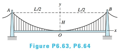
The two main cables of the Akashi Kaikyo suspension bridge in Japan have a span
Expert Solution & Answer

Trending nowThis is a popular solution!

Students have asked these similar questions
Find the magnitude and location of the resultant force on the cylindrical arc
shown in Fig. (10) in each of the following two case:
a. Pg=120.11 KPa (abs)
b. Pg=90.68 KPa (abs)
The arc is 25m long (normal to the paper)
Find the support reacions and joint force of the construction shown on the figure, if; P=12 kN q=9 kN/m M=12 kN and L=2 m
The three-bar truss in Fig. a is subjected to a horizontal force of 5 kip. If the cross-sectional area of each member is 0.20 in2, determine the horizontal displacement at point B. E = 29(103) ksi.
Chapter 6 Solutions
International Edition---engineering Mechanics: Statics, 4th Edition
Ch. 6 - Determine the internal force system acting on...Ch. 6 - Determine the internal force system acting on...Ch. 6 - Determine the internal force system acting on...Ch. 6 - Find the internal force systems acting on sections...Ch. 6 - Find the internal force systems acting on sections...Ch. 6 - Find the internal force systems acting on sections...Ch. 6 - The three identical cantilever beams carry...Ch. 6 - Determine the internal force systems acting on...Ch. 6 - For the structural component shown, determine the...Ch. 6 - Compute the internal force system acting on...
Ch. 6 - Determine the internal force system acting on...Ch. 6 - Determine the internal force systems acting on...Ch. 6 - Determine the internal force systems acting on...Ch. 6 - Find the internal force system acting on section 3...Ch. 6 - The structure is supported by a pin at C and a...Ch. 6 - The 1800lbin. couple is applied to member DEF of...Ch. 6 - A man of weight W climbs a ladder that has been...Ch. 6 - For the ladder in Prob. 6.17, find the internal...Ch. 6 - Determine the internal force system acting on...Ch. 6 - The equation of the parabolic arch is y=(36x2)/6,...Ch. 6 - For the beam shown, derive the expressions for V...Ch. 6 - For the beam shown, derive the expressions for V...Ch. 6 - For the beam shown, derive the expressions for V...Ch. 6 - For the beam shown, derive the expressions for V...Ch. 6 - For the beam shown, derive the expressions for V...Ch. 6 - For the beam shown, derive the expressions for V...Ch. 6 - For the beam shown, derive the expressions for V...Ch. 6 - For the beam shown, derive the expressions for V...Ch. 6 - For the beam shown, derive the expressions for V...Ch. 6 - For the beam shown, derive the expressions for V...Ch. 6 - For the beam shown, derive the expressions for V...Ch. 6 - For the beam shown, derive the expressions for V...Ch. 6 - For the beam shown, derive the expressions for V...Ch. 6 - For the beam shown, derive the expressions for V...Ch. 6 - For the beam shown, derive the expressions for V...Ch. 6 - For the beam shown, derive the expressions for V...Ch. 6 - For the beam shown, derive the expressions for V...Ch. 6 - For the beam shown, derive the expressions for V...Ch. 6 - Derive the shear force and the bending moment as...Ch. 6 - Derive the shear force and the bending moment as...Ch. 6 - The 24-ft timber floor joist is designed to carry...Ch. 6 - For the beam AB shown in Cases 1 and 2, derive and...Ch. 6 - Construct the shear force and bending moment...Ch. 6 - Construct the shear force and bending moment...Ch. 6 - Construct the shear force and bending moment...Ch. 6 - Construct the shear force and bending moment...Ch. 6 - Construct the shear force and bending moment...Ch. 6 - Construct the shear force and bending moment...Ch. 6 - Construct the shear force and bending moment...Ch. 6 - Construct the shear force and bending moment...Ch. 6 - Construct the shear force and bending moment...Ch. 6 - Construct the shear force and bending moment...Ch. 6 - Construct the shear force and bending moment...Ch. 6 - Construct the shear force and bending moment...Ch. 6 - Construct the shear force and bending moment...Ch. 6 - Construct the shear force and bending moment...Ch. 6 - Draw the load and the bending moment diagrams that...Ch. 6 - Draw the load and the bending moment diagrams that...Ch. 6 - Draw the load and the bending moment diagrams that...Ch. 6 - Draw the load and the bending moment diagrams that...Ch. 6 - Draw the load and the bending moment diagrams that...Ch. 6 - Show that the tension acting at a point in a...Ch. 6 - The cable of the suspension bridge spans L=140m...Ch. 6 - The two main cables of the Akashi Kaikyo...Ch. 6 - Cable AB supports the uniformly distributed load...Ch. 6 - A uniform 80-ft pipe that weighs 960 lb is...Ch. 6 - The cable AB supports a uniformly distributed load...Ch. 6 - The string attached to the kite weighs 0.4 oz/ft....Ch. 6 - Show that the tension acting at a point in a...Ch. 6 - A uniform cable weighing 16 N/m is suspended from...Ch. 6 - The tensions in the cable at points O and B are...Ch. 6 - The cable AOB weighs 24 N/m. Determine the sag H...Ch. 6 - The cable of mass 1.8 kg/m is attached to a rigid...Ch. 6 - One end of cable AB is fixed, whereas the other...Ch. 6 - The end of a water hose weighing 0.5 lb/ft is...Ch. 6 - The 50-ft measuring tape weighs 2.4 lb. Compute...Ch. 6 - The cable AOB weighs 5.2 N/m. When the horizontal...Ch. 6 - The chain OA is 25 ft long and weighs 5 lb/ft....Ch. 6 - The 110-lb traffic light is suspended from two...Ch. 6 - The cable carrying 60-lb loads at B and C is held...Ch. 6 - The cable ABCD is held in the position shown by...Ch. 6 - Find the forces in the three cable segments and...Ch. 6 - The cable carrying three 400-lb loads has a sag at...Ch. 6 - The cable supports three 400-lb loads as shown. If...Ch. 6 - Cable ABC of length 5 m supports the force W at B....Ch. 6 - When the 12-kN load and the unknown force P are...Ch. 6 - The cable is loaded by an 80-lb vertical force at...Ch. 6 - The 15-m-long cable supports the loads W1 and W2...Ch. 6 - The cable of length 15 m supports the forces...Ch. 6 - The 14-kN weight is suspended from a small pulley...Ch. 6 - For the cable ABCD determine (a) the angles 2 and...
Knowledge Booster


Learn more about
Need a deep-dive on the concept behind this application? Look no further. Learn more about this topic, mechanical-engineering and related others by exploring similar questions and additional content below.Similar questions
- The compound beam is supported by a roller at point C, fixed at point A, and the two sections are pinned at point B. It is subjected to a free couple moment M, a distributed load with maximum load intensity w, and a concentrated force F. If the distributed load w = 0.6 kN/m, the concentrated force F = 0.6 kN, and the free couple moment M = 0.8, determine the magnitude of the support reaction (in kN) at pin B. Answer must include 2 places after the decimal point.arrow_forwardA tie plate is used to transmit three-bar forces to a beam as shown in the figure. The modulus of the resultant R of the three forces is 100 kN. If the force F1 has a modulus of 20 kN, determine the moduli of the forces F2 and F3arrow_forwardDetermine the internal forces at point D of the frame shown in the figure.arrow_forward
- The bar supported by a pin at B and a cable at A carries a load of 260 N at C. Neglecting the weight of the bar,a.) Determine the normal force 7 m from A.b.) Determine the shear force 7 m from A.c.) Determine the bending moment 7 m from Ad.) Determine the torsion 7 m from A SHOW COMPLETE SOLUTIONS DRAW FBDarrow_forwardA cylindrical brick chimney of height H weighs w = 825 lb/ft of height (see figure). The inner and outer diameters are d1= 3 ft and d2= 4 ft, respectively. The wind pressure against the side of the chimney is p = 10 lb/ft2 of projected area. Determine the maximum height H if there is to be no tension in the brickwork.arrow_forwardThe bar supported by a pin at A and a cable at Bcarries a load of 260 N at C. Neglecting the weight of the bar,a.) Determine the normal force 3 m from A.b.) Determine the shear force 3 m from A.c.) Determine the bending moment 3 m from Ad.) Determine the torsion 3 m from Aarrow_forward
- An aluminum pole for a street light weighs4600 N and supports an arm that weighs 660 N (seefigure). The center of gravity of the arm is 1.2 m from theaxis of the pole. A wind force of 300 N also acts in the (-y)direction at 9 m above the base. The outside diameter ofthe pole (at its base) is 225 mm, and its thickness is 18 mm. Determine the maximum tensile and compressivestresses σt and σc, respectively, in the pole (at its base)due to the weights and the wind force.arrow_forwardA traffic signal is shown in the figure below. There are two traffic lights A and B, attached to a 5m long overhang at a height of 6m from ground. The weight of each light is given to be 100N. Due to heavy winds there is a net force of 20N on each light acting along the z direction. Approximate the curved overhang by a straight line and determine the moment acting at the ground support G due to these forces.arrow_forwardP=650N d=0.20m h=0.35m What are the Y components of the forces at B and C?arrow_forward
- A cable with supports at the same elevation has a span of 300m. The cable weighs 75 N/m and the sag at midspan is 75 m. Determine The length of the cable.arrow_forwardTHE TWO MAIN CABLES OF THE AKASHI KAIYO SUSPENSIONBRIDGE IN JAPAN HAVE A SPAN L= 1990m AND A SAG H = 233m.THE LOADING ON EACH CABLE ISWO = 444.7 KN/m (withouttraffic) ALONG THE HORIZONTAL. DETERMINE THE CORRESPONDING MAXIMUM FORCE IN ONE OF THE CABLES. Give: Given, FBD, AND solutionarrow_forwardDraw the shear force and moment diagram between AB, assuming the earth pressure to the foundation AB as uniformly distributed.arrow_forward
arrow_back_ios
SEE MORE QUESTIONS
arrow_forward_ios
Recommended textbooks for you
 Mechanics of Materials (MindTap Course List)Mechanical EngineeringISBN:9781337093347Author:Barry J. Goodno, James M. GerePublisher:Cengage Learning
Mechanics of Materials (MindTap Course List)
Mechanical Engineering
ISBN:9781337093347
Author:Barry J. Goodno, James M. Gere
Publisher:Cengage Learning
Mechanics of Materials Lecture: Beam Design; Author: UWMC Engineering;https://www.youtube.com/watch?v=-wVs5pvQPm4;License: Standard Youtube License