
International Edition---engineering Mechanics: Statics, 4th Edition
4th Edition
ISBN: 9781305501607
Author: Andrew Pytel And Jaan Kiusalaas
Publisher: CENGAGE L
expand_more
expand_more
format_list_bulleted
Concept explainers
Videos
Textbook Question
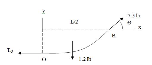
Chapter 6, Problem 6.76P
The 50-ft measuring tape weighs 2.4 lb. Compute the span L of the tape to four significant figures.
Expert Solution & Answer
Want to see the full answer?
Check out a sample textbook solution
Students have asked these similar questions
please show complete solution
Given: W = 656 lb
Convert 4.58 x 10^3 cm^3 to L.
Compute Ix and It for the region shown.
Chapter 6 Solutions
International Edition---engineering Mechanics: Statics, 4th Edition
Ch. 6 - Determine the internal force system acting on...Ch. 6 - Determine the internal force system acting on...Ch. 6 - Determine the internal force system acting on...Ch. 6 - Find the internal force systems acting on sections...Ch. 6 - Find the internal force systems acting on sections...Ch. 6 - Find the internal force systems acting on sections...Ch. 6 - The three identical cantilever beams carry...Ch. 6 - Determine the internal force systems acting on...Ch. 6 - For the structural component shown, determine the...Ch. 6 - Compute the internal force system acting on...
Ch. 6 - Determine the internal force system acting on...Ch. 6 - Determine the internal force systems acting on...Ch. 6 - Determine the internal force systems acting on...Ch. 6 - Find the internal force system acting on section 3...Ch. 6 - The structure is supported by a pin at C and a...Ch. 6 - The 1800lbin. couple is applied to member DEF of...Ch. 6 - A man of weight W climbs a ladder that has been...Ch. 6 - For the ladder in Prob. 6.17, find the internal...Ch. 6 - Determine the internal force system acting on...Ch. 6 - The equation of the parabolic arch is y=(36x2)/6,...Ch. 6 - For the beam shown, derive the expressions for V...Ch. 6 - For the beam shown, derive the expressions for V...Ch. 6 - For the beam shown, derive the expressions for V...Ch. 6 - For the beam shown, derive the expressions for V...Ch. 6 - For the beam shown, derive the expressions for V...Ch. 6 - For the beam shown, derive the expressions for V...Ch. 6 - For the beam shown, derive the expressions for V...Ch. 6 - For the beam shown, derive the expressions for V...Ch. 6 - For the beam shown, derive the expressions for V...Ch. 6 - For the beam shown, derive the expressions for V...Ch. 6 - For the beam shown, derive the expressions for V...Ch. 6 - For the beam shown, derive the expressions for V...Ch. 6 - For the beam shown, derive the expressions for V...Ch. 6 - For the beam shown, derive the expressions for V...Ch. 6 - For the beam shown, derive the expressions for V...Ch. 6 - For the beam shown, derive the expressions for V...Ch. 6 - For the beam shown, derive the expressions for V...Ch. 6 - For the beam shown, derive the expressions for V...Ch. 6 - Derive the shear force and the bending moment as...Ch. 6 - Derive the shear force and the bending moment as...Ch. 6 - The 24-ft timber floor joist is designed to carry...Ch. 6 - For the beam AB shown in Cases 1 and 2, derive and...Ch. 6 - Construct the shear force and bending moment...Ch. 6 - Construct the shear force and bending moment...Ch. 6 - Construct the shear force and bending moment...Ch. 6 - Construct the shear force and bending moment...Ch. 6 - Construct the shear force and bending moment...Ch. 6 - Construct the shear force and bending moment...Ch. 6 - Construct the shear force and bending moment...Ch. 6 - Construct the shear force and bending moment...Ch. 6 - Construct the shear force and bending moment...Ch. 6 - Construct the shear force and bending moment...Ch. 6 - Construct the shear force and bending moment...Ch. 6 - Construct the shear force and bending moment...Ch. 6 - Construct the shear force and bending moment...Ch. 6 - Construct the shear force and bending moment...Ch. 6 - Draw the load and the bending moment diagrams that...Ch. 6 - Draw the load and the bending moment diagrams that...Ch. 6 - Draw the load and the bending moment diagrams that...Ch. 6 - Draw the load and the bending moment diagrams that...Ch. 6 - Draw the load and the bending moment diagrams that...Ch. 6 - Show that the tension acting at a point in a...Ch. 6 - The cable of the suspension bridge spans L=140m...Ch. 6 - The two main cables of the Akashi Kaikyo...Ch. 6 - Cable AB supports the uniformly distributed load...Ch. 6 - A uniform 80-ft pipe that weighs 960 lb is...Ch. 6 - The cable AB supports a uniformly distributed load...Ch. 6 - The string attached to the kite weighs 0.4 oz/ft....Ch. 6 - Show that the tension acting at a point in a...Ch. 6 - A uniform cable weighing 16 N/m is suspended from...Ch. 6 - The tensions in the cable at points O and B are...Ch. 6 - The cable AOB weighs 24 N/m. Determine the sag H...Ch. 6 - The cable of mass 1.8 kg/m is attached to a rigid...Ch. 6 - One end of cable AB is fixed, whereas the other...Ch. 6 - The end of a water hose weighing 0.5 lb/ft is...Ch. 6 - The 50-ft measuring tape weighs 2.4 lb. Compute...Ch. 6 - The cable AOB weighs 5.2 N/m. When the horizontal...Ch. 6 - The chain OA is 25 ft long and weighs 5 lb/ft....Ch. 6 - The 110-lb traffic light is suspended from two...Ch. 6 - The cable carrying 60-lb loads at B and C is held...Ch. 6 - The cable ABCD is held in the position shown by...Ch. 6 - Find the forces in the three cable segments and...Ch. 6 - The cable carrying three 400-lb loads has a sag at...Ch. 6 - The cable supports three 400-lb loads as shown. If...Ch. 6 - Cable ABC of length 5 m supports the force W at B....Ch. 6 - When the 12-kN load and the unknown force P are...Ch. 6 - The cable is loaded by an 80-lb vertical force at...Ch. 6 - The 15-m-long cable supports the loads W1 and W2...Ch. 6 - The cable of length 15 m supports the forces...Ch. 6 - The 14-kN weight is suspended from a small pulley...Ch. 6 - For the cable ABCD determine (a) the angles 2 and...
Knowledge Booster


Learn more about
Need a deep-dive on the concept behind this application? Look no further. Learn more about this topic, mechanical-engineering and related others by exploring similar questions and additional content below.Similar questions
- Using the method of composite areas, find the dimension h that maximizes the centroid coordinate y of the plane region shown.arrow_forwardFind the elevation h (km) where the weight of an object is one-tenth its weight on the surface of the earth.arrow_forwardTwo 12-kg spheres are placed 400 mm apart. Express the gravitational attraction acting between the spheres as a percentage of their weights on earth.arrow_forward
- The center of gravity of the plane wire figure is located at G. Determine the lengths a and b.arrow_forwardFigure (a) shows the cross section of a column that uses a structural shape known as W867 (wide-flange beam, nominally 8 in. deep, weighing 67 lb/ft). The American Institute of Steel Construction Structural Steel Handbook lists the following cross-sectional properties: A=19.7in.2,Ix=272in.4, and Iy=88.6in.4. Determine the dimensions of the rectangle in Fig. (b) that has the same Ix and Iy as a W867 section.arrow_forwardDetermine the maximum value of b (lb/ft) if the roller at point A can only support upto 116 lb. The beam is 17 ft long while c=5.2 ft and a=2.4 ft. Round off only on the final answer expressed in 3 decimals.arrow_forward
- the height of the frame is 50 ftarrow_forwardFind the value of P and the distance x so that the bar AB remains horizontal. Take the radius of the pulleys as 80 mm.arrow_forwardA car weighing 2000 lb, with a wheel base of 9 ft, carries 1600 lb of its load on the front wheels. Compute the maximum moment in lb-ft when crossing a 14-ft span.arrow_forward
- DRAW FREE BODY DIAGRAM DETERMINE THE AMOUNT OF NORMAL FORCES EXERTED ON THE CONTAINER. ANSWER IN 2 DECIMAL PLACESarrow_forwardThe crest gate shown consists of cylindrical surface of which AB is the trace, supported by a structural frame hinged at C. The length of the gate is 9 m. Compute the horizontal force acting on AB.arrow_forwardCalculate all the forces acting on each member of the truss. VERTICAL GRID is equal to 1 meter, and HORIZONTAL GRID is 2.0 marrow_forward
arrow_back_ios
SEE MORE QUESTIONS
arrow_forward_ios
Recommended textbooks for you
 International Edition---engineering Mechanics: St...Mechanical EngineeringISBN:9781305501607Author:Andrew Pytel And Jaan KiusalaasPublisher:CENGAGE L
International Edition---engineering Mechanics: St...
Mechanical Engineering
ISBN:9781305501607
Author:Andrew Pytel And Jaan Kiusalaas
Publisher:CENGAGE L
Everything About COMBINED LOADING in 10 Minutes! Mechanics of Materials; Author: Less Boring Lectures;https://www.youtube.com/watch?v=N-PlI900hSg;License: Standard youtube license