Fundamentals of Electric Circuits
6th Edition
ISBN: 9780078028229
Author: Charles K Alexander, Matthew Sadiku
Publisher: McGraw-Hill Education
bartleby

Concept explainers

bartleby

Videos

Textbook Question
Book Icon
Chapter 6, Problem 74P

The triangular waveform in Fig. 6.91(a) is applied to the input of the op amp differentiator in Fig. 6.91(b). Plot the output.
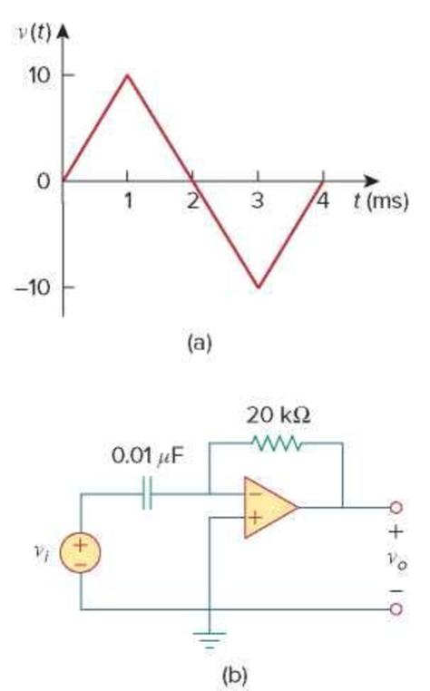
Chapter 6, Problem 74P, The triangular waveform in Fig. 6.91(a) is applied to the input of the op amp differentiator in Fig.

Figure 6.91

For Prob. 6.74.

Expert Solution & Answer
Check Mark
To determine

Sketch the output voltage waveform of an op amp differentiator.

Explanation of Solution

Given data:

Refer to Figure 6.91 in the textbook.

Formula used:

Write the expression to calculate the straight line equation for two points (x1,y1) and (x2,y2).

(yy1)=y2y1x2x1(xx1) (1)

Refer to Figure 6.91(a) in the textbook.

From the given voltage graph, substitute t for x and vi(t) for y in equation (1).

(vi(t)y1)=y2y1x2x1(tx1) (2)

Write the expression to calculate the output voltage of an op amp differentiator.

vo(t)=RCdvi(t)dt (3)

Here,

R is the value of the resistor,

C is the value of the capacitor, and

vi is the input voltage.

Calculation:

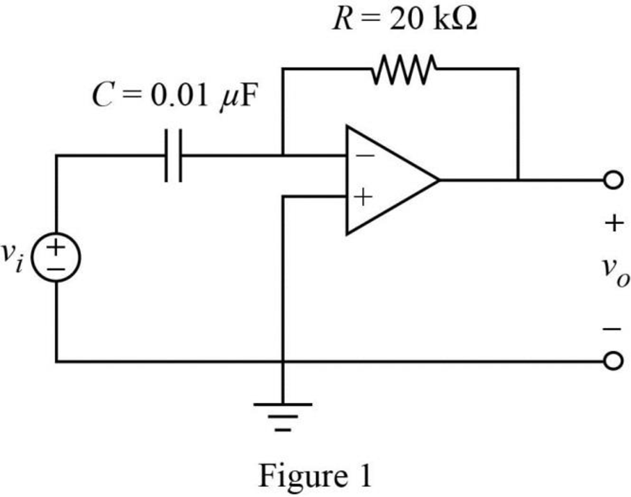
The given circuit is redrawn as Figure 1.

Fundamentals of Electric Circuits, Chapter 6, Problem 74P , additional homework tip  1

Substitute 20kΩ for R and 0.01μF for C in equation (3) to find vo(t).

vo(t)=(20kΩ)(0.01μF)dvi(t)dt=(20×103)(0.01×10⁶)dvi(t)dtΩF {1k=103,1μ=106}

vo(t)=(2×10⁴)dvi(t)dtΩF (4)

The given input voltage waveform is redrawn as Figure 2.

Fundamentals of Electric Circuits, Chapter 6, Problem 74P , additional homework tip  2

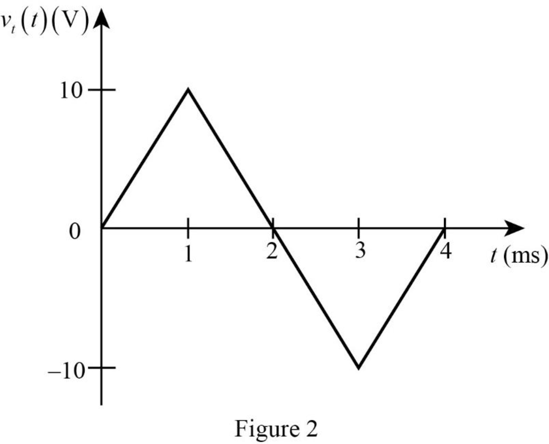
Refer to Figure 2, split up the time period as three divisions such as 0ms<t<1ms, 1ms<t<3ms and 3ms<t<4ms to find the respective voltage value.

Case (i): 0ms<t<1ms

The two points (x1,y1) and (x2,y2) are (0ms,0V) and (1ms,10V).

Substitute 0ms for x1, 0V for y1, 1ms for x2 and 10V for y2 in equation (2) to find vi(t).

(vi(t)0V)=10V0V1ms0ms(t0ms)=10V1ms(t)=101×103(t)V {1m=103}=10000tV

Simplify the equation to find vi(t).

vi(t)=10000tV+0V=10000tV

Case (ii): 1ms<t<3ms

The two points (x1,y1) and (x2,y2) are (1ms,10V) and (3ms,10V).

Substitute 1ms for x1, 10V for y1, 3ms for x2 and 10V for y2 in equation (2) to find vi(t).

(vi(t)10V)=10V10V3ms1ms(t1ms)=20V2ms(t1ms)=20(2×10³)(t(1×10³))V {1m=103}=10000tV+0.02V

Simplify the equation to find vi(t).

vi(t)=10000tV+0.02V+10V=10000tV+10.02V=(10000t+10.02)V

Case (iii): 3ms<t<4ms

The two points (x1,y1) and (x2,y2) are (3ms,10V) and (4ms,0V).

Substitute 3ms for x1, 10V for y1, 4ms for x2 and 0V for y2 in equation (2) to find vi(t).

(vi(t)(10V))=0V(10V)4ms3ms(t3ms)(vi(t)+10V)=10V1ms(t3ms)=101×103(t(3×10³))V {1m=103}=10000tV0.03V

Simplify the equation to find vi(t).

vi(t)=10000tV0.03V10V=10000tV10.03V=(10000t10.03)V

Therefore, the input voltage function vi(t) of the signal in Figure 2 is,

vi(t)={10000tV, 0ms<t<1ms(10000t+10.02)V, 1ms<t<3ms(10000t10.03)V, 3ms<t<4ms

For 0ms<t<1ms:

Substitute 10000tV for vi(t) in equation (4) to find vo(t).

vo(t)=(2×10⁴)d(10000tV)dtΩF=(2×10⁴)(10000)ddt(t)ΩFV=2(1)ΩFVs=2FV(sΩ)

Simplify the equation to find vo(t).

vo(t)=2FVF {1F=1s1Ω}=2V

For 1ms<t<3ms:

Substitute (10000t+10.02)V for vi(t) in equation (4) to find vo(t).

vo(t)=(2×10⁴)d((10000t+10.02)V)dtΩF=(2×10⁴)ddt(10000t+10.02)ΩFV=(2×10⁴)(10000(1)+0)ΩFVs=(2×10⁴)(10000)FV(sΩ)

Simplify the equation to find vo(t).

vo(t)=2FVF {1F=1s1Ω}=2V

For 3ms<t<4ms:

Substitute (10000t10.03)V for vi(t) in equation (4) to find vo(t).

vo(t)=(2×10⁴)d((10000t10.03)V)dtΩF=(2×10⁴)ddt(10000t10.03)ΩFV=(2×10⁴)(10000(1)0)ΩFVs=(2×10⁴)(10000)FV(sΩ)

Simplify the equation to find vo(t).

vo(t)=2FVF {1F=1s1Ω}=2V

Therefore, the output voltage function vo(t) is expressed as,

vo(t)={2V, 0ms<t<1ms2V, 1ms<t<3ms2V, 3ms<t<4ms

The output voltage waveform is drawn as Figure 3.
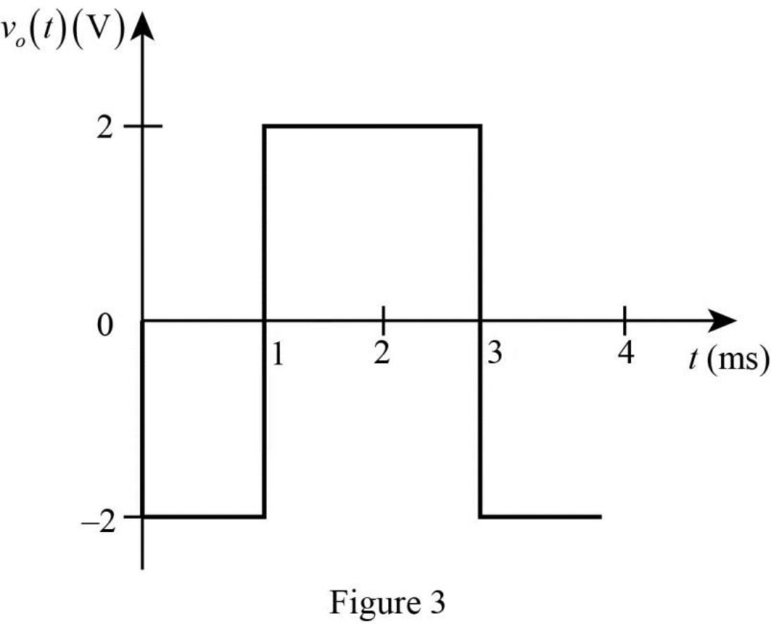
Fundamentals of Electric Circuits, Chapter 6, Problem 74P , additional homework tip  3

Conclusion:

Thus, the output voltage waveform of an op amp differentiator vo(t) is sketched.

Want to see more full solutions like this?

Subscribe now to access step-by-step solutions to millions of textbook problems written by subject matter experts!
Students have asked these similar questions
The voltage source is at a constant level for a long time, which we approximate as infinite.  This is the circuit:   The voltage drop across the capacitor rises from 0 to ℰ.  Note that ℰ is never actually known in the measurement.  In fact, the oscilloscope voltage is decalibrated, so that, whatever ℰ is, ℰ is at the top line while zero is at the bottom line.  We don't measure voltage levels, but rather 1/2, 1/4, and 1/8 the maximum. Kirchhoff's voltage law give: ℰ = IR + Q/C or the following: dQdt=−1RC(Q−EC)dQdt=−1RC(Q−ℰC)  The solution for the capacitor voltage is VC(t)=E(1−e−t/RC)VC(t)=ℰ(1−e−t/RC)  The voltage is zero at t = 0, t is the rising time, and you have to know when the rising begins.
A 100-uF capacitor is charged by a constant current of 1mA. Find the voltage across the capacitor at t = 4s. Assume V(0) = 0 V.
The voltage across a 5-microFarad capacitor is: v(t)=5cos1000t V. Solve the current through it.

Chapter 6 Solutions

Fundamentals of Electric Circuits

Ch. 6.5 - Calculate the equivalent inductance for the...Ch. 6.5 - In the circuit of Fig. 6.34, i1(t) = 3e2t A. If...Ch. 6.6 - The integrator in Fig. 6.35(b) has R = 100 k, C =...Ch. 6.6 - The differentiator in Fig. 6.37 has R = 100 k and...Ch. 6.6 - Design an analog computer circuit to solve the...Ch. 6 - What charge is on a 5-F capacitor when it is...Ch. 6 - Capacitance is measured in: (a)coulombs (b)joules...Ch. 6 - When the total charge in a capacitor is doubled,...Ch. 6 - Can the voltage waveform in Fig. 6.42 be...Ch. 6 - The total capacitance of two 40-mF...Ch. 6 - In Fig. 6.43, if i = cos 4t and v = sin 4t, the...Ch. 6 - A 5-H inductor changes its current by 3 A in 0.2...Ch. 6 - If the current through a 10-mH inductor increases...Ch. 6 - Inductors in parallel can be combined just like...Ch. 6 - Prob. 10RQCh. 6 - If the voltage across a 7.5-F capacitor is 2te3t...Ch. 6 - A 50-F capacitor has energy w(t) = 10 cos2 377t J....Ch. 6 - Design a problem to help other students better...Ch. 6 - A voltage across a capacitor is equal to [2 2...Ch. 6 - The voltage across a 4-F capacitor is shown in...Ch. 6 - The voltage waveform in Fig. 6.46 is applied...Ch. 6 - At t = 0, the voltage across a 25-mF capacitor is...Ch. 6 - A 4-mF capacitor has the terminal voltage v=...Ch. 6 - The current through a 0.5-F capacitor is 6(1 et)...Ch. 6 - The voltage across a 5-mF capacitor is shown in...Ch. 6 - A 4-mF capacitor has the current waveform shown in...Ch. 6 - A voltage of 45e2000t V appears across a parallel...Ch. 6 - Find the voltage across the capacitors in the...Ch. 6 - Series-connected 20- and 60-pF capacitors are...Ch. 6 - Two capacitors (25 and 75 F) are connected to a...Ch. 6 - The equivalent capacitance at terminals a-b in the...Ch. 6 - Determine the equivalent capacitance for each of...Ch. 6 - Find Ceq in the circuit of Fig. 6.52 if all...Ch. 6 - Find the equivalent capacitance between terminals...Ch. 6 - Find the equivalent capacitance at terminals a-b...Ch. 6 - Determine the equivalent capacitance at terminals...Ch. 6 - Obtain the equivalent capacitance of the circuit...Ch. 6 - Using Fig. 6.57, design a problem that will help...Ch. 6 - In the circuit shown in Fig. 6.58 assume that the...Ch. 6 - (a)Show that the voltage-division rule for two...Ch. 6 - Three capacitors, C1 = 5 F, C2 = 10 F, and C3 = 20...Ch. 6 - Given that four 10-F capacitors can be connected...Ch. 6 - Obtain the equivalent capacitance of the network...Ch. 6 - Determine Ceq for each circuit in Fig. 6.61....Ch. 6 - Assuming that the capacitors are initially...Ch. 6 - If v(0) = 0, find v(t), i1(t), and i2(t) in the...Ch. 6 - In the circuit in Fig. 6.64, let is = 4.5e2t mA...Ch. 6 - Obtain the Thevenin equivalent at the terminals,...Ch. 6 - The current through a 25-mH inductor is 10et/2 A....Ch. 6 - An inductor has a linear change in current from...Ch. 6 - Design a problem to help other students better...Ch. 6 - The current through a 12-mH inductor is 4 sin 100t...Ch. 6 - The current through a 40-mH inductor is i(t)= 0,...Ch. 6 - The voltage across a 50-mH inductor is given by...Ch. 6 - The current through a 5-mH inductor is shown in...Ch. 6 - The voltage across a 2-H inductor is 20(1 e2t) V....Ch. 6 - If the voltage waveform in Fig. 6.67 is applied...Ch. 6 - The current in a 150-mH inductor increases from 0...Ch. 6 - A 100-mH inductor is connected in parallel with a...Ch. 6 - If the voltage waveform in Fig. 6.68 is applied to...Ch. 6 - Find vC, iL, and the energy stored in the...Ch. 6 - For the circuit in Fig. 6.70, calculate the value...Ch. 6 - Under steady-state dc conditions, find i and v in...Ch. 6 - Find the equivalent inductance of the circuit in...Ch. 6 - An energy-storage network consists of...Ch. 6 - Determine Leq at terminals a-b of the circuit in...Ch. 6 - Using Fig. 6.74, design a problem to help other...Ch. 6 - Find Leq at the terminals of the circuit in Fig....Ch. 6 - Find the equivalent inductance looking into the...Ch. 6 - Find Leq in each of the circuits in Fig. 6.77....Ch. 6 - Find Leq in the circuit of Fig. 6.78. Figure 6.78...Ch. 6 - Determine Leq that may be used to represent the...Ch. 6 - The current waveform in Fig. 6.80 flows through a...Ch. 6 - (a) For two inductors in series as in Fig....Ch. 6 - In the circuit of Fig. 6.82, io(0) = 2 A....Ch. 6 - Consider the circuit in Fig. 6.83. Find: (a) Leq,...Ch. 6 - Consider the circuit in Fig. 6.84. Given that v(t)...Ch. 6 - In the circuit of Fig. 6.85, sketch vo. Figure...Ch. 6 - The switch in Fig. 6.86 has been in position A for...Ch. 6 - The inductors in Fig. 6.87 are initially charged...Ch. 6 - The current i(t) through a 20-mH inductor is...Ch. 6 - An op amp integrator has R = 50 k and C = 0.04 F....Ch. 6 - A 6-V dc voltage is applied to an integrator with...Ch. 6 - An op amp integrator with R = 4 M and C = 1 F has...Ch. 6 - Using a single op amp, a capacitor, and resistors...Ch. 6 - Show how you would use a single op amp to generate...Ch. 6 - At t = 1.5 ms, calculate vo due to the cascaded...Ch. 6 - Show that the circuit in Fig. 6.90 is a...Ch. 6 - The triangular waveform in Fig. 6.91(a) is applied...Ch. 6 - An op amp differentiator has R = 250 k and C = 10...Ch. 6 - A voltage waveform has the following...Ch. 6 - The output vo of the op amp circuit in Fig....Ch. 6 - Prob. 78PCh. 6 - Figure 6.93 presents an analog computer designed...Ch. 6 - Design an analog computer to simulate the...Ch. 6 - Design an op amp circuit such that vo=10vs+2vsdt...Ch. 6 - Your laboratory has available a large number of...Ch. 6 - An 8-mH inductor is used in a fusion power...Ch. 6 - A square-wave generator produces the voltage...Ch. 6 - An electric motor can be modeled as a series...
Knowledge Booster
Background pattern image
Electrical Engineering
Learn more about
Need a deep-dive on the concept behind this application? Look no further. Learn more about this topic, electrical-engineering and related others by exploring similar questions and additional content below.
Similar questions
SEE MORE QUESTIONS
Recommended textbooks for you
Text book image
Introductory Circuit Analysis (13th Edition)
Electrical Engineering
ISBN:9780133923605
Author:Robert L. Boylestad
Publisher:PEARSON
Text book image
Delmar's Standard Textbook Of Electricity
Electrical Engineering
ISBN:9781337900348
Author:Stephen L. Herman
Publisher:Cengage Learning
Text book image
Programmable Logic Controllers
Electrical Engineering
ISBN:9780073373843
Author:Frank D. Petruzella
Publisher:McGraw-Hill Education
Text book image
Fundamentals of Electric Circuits
Electrical Engineering
ISBN:9780078028229
Author:Charles K Alexander, Matthew Sadiku
Publisher:McGraw-Hill Education
Text book image
Electric Circuits. (11th Edition)
Electrical Engineering
ISBN:9780134746968
Author:James W. Nilsson, Susan Riedel
Publisher:PEARSON
Text book image
Engineering Electromagnetics
Electrical Engineering
ISBN:9780078028151
Author:Hayt, William H. (william Hart), Jr, BUCK, John A.
Publisher:Mcgraw-hill Education,
Capacitors Explained - The basics how capacitors work working principle; Author: The Engineering Mindset;https://www.youtube.com/watch?v=X4EUwTwZ110;License: Standard YouTube License, CC-BY