
Concept explainers
Videos
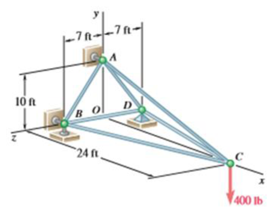
The truss shown consists of six members and is supported by a short link at A. two short links at B, and a ball and socket at D. Determine the force in each of the members for the given loading.
The force in each of the members of the truss for the given loading.
Answer to Problem 6.35P
The force in member AC is
Explanation of Solution
The free-body diagram of the entire truss is shown in figure 1.
Refer to figure 1 and use symmetry.
Here,
Write the equilibrium equations taking the moments about
Here,
Write the equation for
Here,
Put the above equation in equation (II).
The
Here,
Write the expression for
Put the above equation in equation (III).
Put equation (I) in the above equation.
Substitute
The
Here,
Write the expression for
Put the above equation in equation (IV).
Put equation (I) in the above equation.
Write the expression for the reaction at the point B.
Here
Substitute
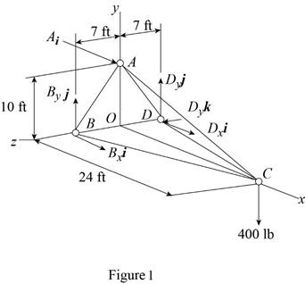
Consider the free-body joint C. The free-body diagram of joint C is shown in figure 2.
Refer to figure (2) and write the expression for the forces.
Here,
Write the expression for
Find the magnitude of
Substitute
Write the expression for
Here,
Substitute
Write the expression for
Here,
Substitute
The net force must be equal to zero.
Here,
Write the expression for
Put the above equation in equation (IX).
Put equations (VI), (VII) and (VIII) in the above equation.
Equate the coefficient of
Equate the coefficient of
Equate the coefficient of
Put the above equation in equation (XI).
Substitute
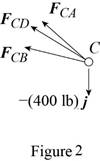
Consider the free-body joint B. The free-body diagram of joint B is shown in figure 3.
Refer to figure (3) and write the expression for the forces.
Here,
Substitute
Write the expression for
Here,
Substitute
Write the expression for
Here,
Write the expression for
Put the above equation in equation (IX).
Put equations (XIV), (XV) and (XVI) in the above equation.
Substitute
Equate the coefficient of
Equate the coefficient of
Substitute
From symmetry,
Here,
Substitute
Conclusion:
Thus, the force in member AC is
Want to see more full solutions like this?
Chapter 6 Solutions
Vector Mechanics for Engineers: Statics


- A couple acting on the winch at G slowly raises the load W by means of a rope that runs around the pulleys attached to the derrick at A and B. Determine the forces in members EF and KL of the derrick, assuming the diameters of the pulleys and the winch are negligible.arrow_forwardFor the pliers shown, determine the relationship between the magnitudes of the applied forces P and the gripping forces at E.arrow_forwardA hoist is formed by connecting bars BD and BE to member ABC. Neglecting the weights of the members and assuming that all connections are ball-and-socket joints, determine the magnitudes of the forces in bars BD and BE caused by the 480-N vertical force.arrow_forward
- Compute the magnitude of the pin reaction at B. Neglect the weights of the structural members.arrow_forwardThe 180-lb homogeneous bar is supported by a ball-and-socket joint at A and two cables attached to B. Determine the forces in the cables.arrow_forwardFind the forces in members CD, DH, and HI.arrow_forward
- Find the force P required to (a) push; and (b) pull the 80-lb homogeneous roller over the 3-in. curb.arrow_forwardThe homogeneous 80-kg sign is suspended from a ball-and-socket joint at O, and cables AD and BC. Determine the forces in the cables.arrow_forwardThe 180-kg uniform boom ABC, supported by a horizontal cable at B and a pin at A, carries a 320-kg load at C. Determine the force in the cable and the magnitude of the pin reaction.arrow_forward
 International Edition---engineering Mechanics: St...Mechanical EngineeringISBN:9781305501607Author:Andrew Pytel And Jaan KiusalaasPublisher:CENGAGE L