Vector Mechanics for Engineers: Statics
12th Edition
ISBN: 9781259977268
Author: Ferdinand P. Beer, E. Russell Johnston Jr., David Mazurek
Publisher: McGraw-Hill Education
bartleby

Videos

Textbook Question
Book Icon
Chapter 6.3, Problem 6.121P

6.119 through 6.121 Each of the frames shown consists of two L-shaped members connected by two rigid links. For each frame, determine the reactions at the supports and indicate whether the frame is rigid.
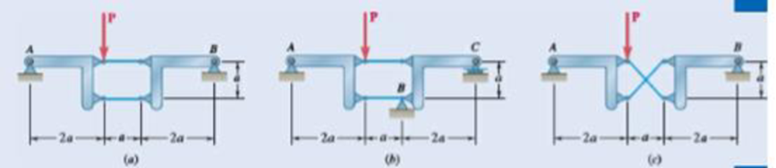
Chapter 6.3, Problem 6.121P, 6.119 through 6.121 Each of the frames shown consists of two L-shaped members connected by two rigid

Fig. P6.121

Expert Solution & Answer
Check Mark
To determine

The reactions at the frame and the rigidness of the frame.

Answer to Problem 6.121P

The reactions at the frame for figure (a) is B=2P_ towards right, A=2.24P_ at 26.6°_ above the positive x axis and the rigidness of the frame in figure (a) rigid, for figure (b) the reaction is P=0 and the system is not rigid, and for figure (c) the reactions are A=P_ upwards, C=P_ upwards, B=P_ and the system is rigid.

Explanation of Solution

The following figure gives the free body diagram of the first part of the member in figure P6.121(a).

Vector Mechanics for Engineers: Statics, Chapter 6.3, Problem 6.121P , additional homework tip  1

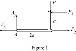
Write the equation to find the moment of force.

M=Fa

Here, F is the force acting and a is the perpendicular distance from the force to the point about which the moment is calculated.

Write the equation to find the total moment about the point A.

ΣMA=Σ(Fa)

Write the equations for equilibrium for the free body diagram in figure 1.

ΣMA=0 (I)

ΣFx=0 (II)

ΣFy=0 (III)

Here, MA is the torque about the point A, Fy is the force in the y direction, and Fx is the force in the x direction.

The following figure gives the free body diagram of the second part of the member in figure P6.121(a).

Vector Mechanics for Engineers: Statics, Chapter 6.3, Problem 6.121P , additional homework tip  2

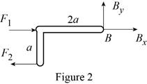
Write the equations for equilibrium for the free body diagram in figure 2.

ΣMB=0 (IV)

ΣFx=0 (V)

ΣFy=0 (VI)

Here, Fx is the force in the x direction, Fy is the force in the y direction and MB is the torque about the point B.

The following figure gives the free body diagram of the first part of the member in figure P6.119(b).

Vector Mechanics for Engineers: Statics, Chapter 6.3, Problem 6.121P , additional homework tip  3

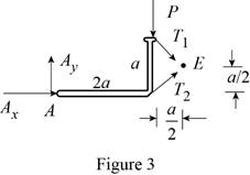
Write the equations for equilibrium for the free body diagram in figure 3.

ΣME=0 (VII)

Here, ME is the torque about the point E.

The following figure gives the free body diagram of the second part of the member in figure P6.119(b).

Vector Mechanics for Engineers: Statics, Chapter 6.3, Problem 6.121P , additional homework tip  4

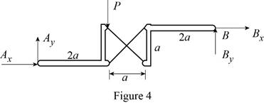
Write the equations for equilibrium for the free body diagram in figure 4.

ΣMB=0 (VIII)

Here, MB is the torque about the point B.

The following figure gives the free body diagram of the member in figure P6.119(c).

Vector Mechanics for Engineers: Statics, Chapter 6.3, Problem 6.121P , additional homework tip  5

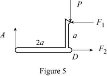
Write the equations for equilibrium for the free body diagram in figure 5.

ΣFy=0 (IX)

ΣMD=0 (X)

ΣFx=0 (XI)

Here, MD is the torque about the point D, Fx is the force in the x direction, and Fy is the force in the y direction.

The following figure gives the free body diagram of right part of the member in figure P6.119(c).

Vector Mechanics for Engineers: Statics, Chapter 6.3, Problem 6.121P , additional homework tip  6

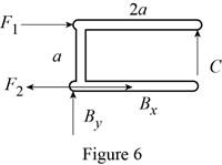
Write the equations for equilibrium for the free body diagram in figure 6.

ΣMD=0 (XII)

ΣFx=0 (XIII)

Here, MD is the torque about the point D, and Fx is the force in the x direction.

Write the expression to find the magnitude of the vector from its components.

C=Cx2+Cy2 (XIV)

Here,Cx is the x component of the vector C and Cy is the y component of the vector C.

Write the equation to find the angle of orientation of the vector C.

θ=tan1(CyCx) (XV)

Conclusion:

Solve equation (I) using figure 1.

aF12aP=0

Rewrite the above equation.

F1=2P

Solve equation (III) using figure 1.

AyP=0

Rewrite the above equation.

Ay=P

Solve equation (IV) using figure 2.

aF2=0

Rewrite the above equation.

F2=0

Solve equation (V) using figure 2.

Bx+F1=0

Substitute 2P for F1 and rewrite the above equation to find Bx.

Bx=F1=2P

Solve equation (VI) using figure 2.

AxF1+F2=0

Substitute 2P for F1, 0 for F2 and rewrite the above equation to find Ax.

Ax=F1+F2=2P+0=2P

Rewrite equation (XIV) in terms of the vector A.

A=Ax2+Ay2

Substitute 2P for Ax, and P for Ay in the above equation.

A=(2P)2+(P)2=2.236P

Rewrite equation (XV) in terms of the vector A.

θ=tan1(AyAx)

Substitute 2P for Ax, and P for Ay in the above equation.

θ=tan1(P2P)=26.56°

Rewrite equation (XIV) in terms of the vector B.

B=Bx2+By2

Substitute 2P for Bx, and 0 for By in the above equation.

B=(2P)2+(0)2=2P

Solve equation (VII) using figure 3.

a2P+a2Ax5a2Ay=0

Rewrite the above equation.

Ax5Ay=P

Solve equation (VIII) using figure 4.

3aP+aAx5aAy=0

Rewrite the above equation.

Ax5Ay=3P

Solve the conditions obtained from figure 3 and 4.

P=0

Solve equation (IX) using figure 5.

AP=0

Rewrite the above equation to find A.

A=P

Solve equation (X) using figure 5.

aF12aA=0

Substitute P for A and rewrite the above equation to find F1.

F1=2P

Solve equation (XI) using figure 5.

F2F1=0

Substitute 2P for F1 and rewrite the above equation to find F2.

F2=F1=2P

Solve equation (XII) using figure 6.

2aCaF1=0

Substitute 2P for F1 and rewrite the above equation to find C.

C=F12=P

Solve equation (XII) to the right using figure 6.

F1F2+Bx=0

Substitute 2P for F1, 2P for F2 and rewrite the above equation to find Bx.

Bx=F1+F2=2P+2P=0

Solve equation (XII) upwards using figure 6.

Bx+C=0

Substitute P for C and rewrite the above equation to find Bx.

Bx=C=P

Therefore, the reactions at the frame for figure (a) is B=2P_ towards right, A=2.24P_ at 26.6°_ above the positive x axis and the rigidness of the frame in figure (a) rigid, for figure (b) the reaction is P=0 and the system is not rigid, and for figure (c) the reactions are A=P_ upwards, C=P_ upwards, B=P_ and the system is rigid.

Want to see more full solutions like this?

Subscribe now to access step-by-step solutions to millions of textbook problems written by subject matter experts!
Students have asked these similar questions
The assembly shown consists of an 80-mm rod AF that is welded to a cross frame consisting of four 200-mm arms. The assembly is supported by a ball-and-socket joint at F and by three short links, each of which forms an angle of 45° with the vertical. For the loading shown, determine (a) the tension in each link, (b) the reaction at F.
The cab and motor units of the front-end loader shown are connected by a vertical pin located 2 m behind the cab wheels. The distance from C to D is 1 m. The center of gravity of the 300-kN motor unit is located at Gm , while the centers of gravity of the 100-kN cab and 75-kN load are located, respectively, at Gc and GI. . Knowing that the machine is at rest with its brakes released, determine (a) the reactions at each of the four wheels, (b) the forces exerted on the motor unit at C and D.
The cab and motor units of the front-end loader shown are connected by a vertical pin located 2 m behind the cab wheels. The distance from C to D is 1 m. The center of gravity of the 300-kN motor unit is located at Gm, while the centers of gravity of the 100-kN cab and 75-kN load are located, respectively, at Gc and Gl. Knowing that the front-end loader is at rest with its brakes released, determine(a) the reactions at each of the four wheels, (b) the forces exertedon the motor unit at C and D.

Chapter 6 Solutions

Vector Mechanics for Engineers: Statics

Ch. 6.1 - Determine the force in each member of the Gambrel...Ch. 6.1 - Determine the force in each member of the Howe...Ch. 6.1 - Using the method of joints, determine the force in...Ch. 6.1 - Prob. 6.14PCh. 6.1 - Determine the force in each member of the Warren...Ch. 6.1 - Solve Problem 6.15 assuming that the load applied...Ch. 6.1 - Determine the force in each member of the Pratt...Ch. 6.1 - The truss shown is one of several supporting an...Ch. 6.1 - Determine the force in each member of the Pratt...Ch. 6.1 - Solve Problem 6.19 assuming that the load applied...Ch. 6.1 - Determine the force in each of the members located...Ch. 6.1 - Determine the force in member DE and in each of...Ch. 6.1 - Determine the force in each of the members located...Ch. 6.1 - The portion of truss shown represents the upper...Ch. 6.1 - For the tower and loading of Prob. 6.24 and...Ch. 6.1 - Solve Problem 6.24 assuming that the cables...Ch. 6.1 - Determine the force in each member of the truss...Ch. 6.1 - Determine the force in each member of the truss...Ch. 6.1 - Determine whether the trusses of Problems 6.31a,...Ch. 6.1 - Determine whether the trusses of Problems 6.31b,...Ch. 6.1 - For the given loading, determine the zero-force...Ch. 6.1 - For the given loading, determine the zero-force...Ch. 6.1 - For the given loading, determine the zero-force...Ch. 6.1 - Determine the zero-force members in the truss of...Ch. 6.1 - The truss shown consists of six members and is...Ch. 6.1 - The truss shown consists of six members and is...Ch. 6.1 - The truss shown consists of six members and is...Ch. 6.1 - Prob. 6.38PCh. 6.1 - The truss shown consists of nine members and is...Ch. 6.1 - Solve Prob. 6.39 for P = 0 and Q = (900 N)k. 6.39...Ch. 6.1 - The truss shown consists of 18 members and is...Ch. 6.1 - The truss shown consists of 18 members and is...Ch. 6.2 - Determine the force in members BD and DE of the...Ch. 6.2 - Determine the force in members DG and EG of the...Ch. 6.2 - Determine the force in members BD and CD of the...Ch. 6.2 - Determine the force in members DF and DG of the...Ch. 6.2 - A floor truss is loaded as shown. Determine the...Ch. 6.2 - A floor truss is loaded as shown. Determine the...Ch. 6.2 - Determine the force in members CD and DF of the...Ch. 6.2 - Determine the force in members CE and EF of the...Ch. 6.2 - Determine the force in members DE and DF of the...Ch. 6.2 - Determine the force in members EG and EF of the...Ch. 6.2 - Determine the force in members DF and DE of the...Ch. 6.2 - Determine the force in members CD and CE of the...Ch. 6.2 - A Pratt roof truss is loaded as shown. Determine...Ch. 6.2 - A Pratt roof truss is loaded as shown. Determine...Ch. 6.2 - A Howe scissors roof truss is loaded as shown....Ch. 6.2 - A Howe scissors roof truss is loaded as shown....Ch. 6.2 - Determine the force in members AD, CD, and CE of...Ch. 6.2 - Determine the force in members DG, FG, and FH of...Ch. 6.2 - Determine the force in member GJ of the truss...Ch. 6.2 - Determine the force in members DG and FH of the...Ch. 6.2 - Prob. 6.63PCh. 6.2 - Prob. 6.64PCh. 6.2 - The diagonal members in the center panels of the...Ch. 6.2 - The diagonal members in the center panels of the...Ch. 6.2 - The diagonal members in the center panels of the...Ch. 6.2 - Solve Prob. 6.67 assuming that the 9-kip load has...Ch. 6.2 - Classify each of the structures shown as...Ch. 6.2 - Classify each of the structures shown as...Ch. 6.2 - 6.70 through 6.74 classify as determinate or...Ch. 6.2 - 6.70 through 6.74 classify as determinate or...Ch. 6.2 - 6.70 through 6.74 classify as determinate or...Ch. 6.2 - 6.70 through 6.74 classify as determinate or...Ch. 6.3 - For the frame and loading shown, draw the...Ch. 6.3 - For the frame and loading shown, draw the...Ch. 6.3 - Draw the free-body diagram(s) needed to determine...Ch. 6.3 - Knowing that the pulley has a radius of 0.5 m,...Ch. 6.3 - and 6.76 Determine the force in member BD and the...Ch. 6.3 - Prob. 6.76PCh. 6.3 - For the frame and loading shown, determine the...Ch. 6.3 - Determine the components of all forces acting on...Ch. 6.3 - The hydraulic cylinder CF, which partially...Ch. 6.3 - The hydraulic cylinder CF, which partially...Ch. 6.3 - Determine the components of all forces acting on...Ch. 6.3 - Determine the components of all forces acting on...Ch. 6.3 - Determine the components of the reactions at A and...Ch. 6.3 - Determine the components of the reactions at D and...Ch. 6.3 - Determine the components of the reactions at A and...Ch. 6.3 - Determine the components of the reactions at A and...Ch. 6.3 - Determine the components of the reactions at A and...Ch. 6.3 - The 48-lb load can be moved along the line of...Ch. 6.3 - The 48-lb load is removed and a 288-lb in....Ch. 6.3 - (a) Show that, when a frame supports a pulley at...Ch. 6.3 - Knowing that each pulley has a radius of 250 mm,...Ch. 6.3 - Knowing that the pulley has a radius of 75 mm,...Ch. 6.3 - Prob. 6.93PCh. 6.3 - Prob. 6.94PCh. 6.3 - A trailer weighing 2400 lb is attached to a...Ch. 6.3 - In order to obtain a better weight distribution...Ch. 6.3 - The cab and motor units of the front-end loader...Ch. 6.3 - Solve Problem 6.97 assuming that the 75-kN load...Ch. 6.3 - Knowing that P = 90 lb and Q = 60 lb, determine...Ch. 6.3 - Knowing that P = 90 lb and Q = 60 lb, determine...Ch. 6.3 - For the frame and loading shown, determine the...Ch. 6.3 - For the frame and loading shown, determine the...Ch. 6.3 - Prob. 6.103PCh. 6.3 - Prob. 6.104PCh. 6.3 - For the frame and loading shown, determine the...Ch. 6.3 - Solve Prob. 6.105 assuming that the 6-kN load has...Ch. 6.3 - The axis of the three-hinge arch ABC is a parabola...Ch. 6.3 - The axis of the three-hinge arch ABC is a parabola...Ch. 6.3 - 6.109 and 6.110 Neglecting the effect of friction...Ch. 6.3 - and 6.110 Neglecting the effect of friction at the...Ch. 6.3 - 6.111, 6.112, and 6.113 Members ABC and CDE are...Ch. 6.3 - 6.111, 6.112, and 6.113 Members ABC and CDE are...Ch. 6.3 - 6.111, 6.112, and 6.113 Members ABC and CDE are...Ch. 6.3 - Members ABC and CDE are pin-connected at C and...Ch. 6.3 - Solve Prob. 6.112 assuming that the force P is...Ch. 6.3 - Solve Prob. 6.114 assuming that the force P is...Ch. 6.3 - Four beams, each with a length of 2a, are nailed...Ch. 6.3 - Four beams, each with a length of 3a, are held...Ch. 6.3 - 6.119 through 6.121 Each of the frames shown...Ch. 6.3 - 6.119 through 6.121 Each of the frames shown...Ch. 6.3 - 6.119 through 6.121 Each of the frames shown...Ch. 6.4 - An 84-lb force is applied to the toggle vise at C....Ch. 6.4 - For the system and loading shown, draw the...Ch. 6.4 - A small barrel weighing 60 lb is lifted by a pair...Ch. 6.4 - The position of member ABC is controlled by the...Ch. 6.4 - The shear shown is used to cut and trim...Ch. 6.4 - A 100-lb force directed vertically downward is...Ch. 6.4 - Prob. 6.124PCh. 6.4 - The control rod CE passes through a horizontal...Ch. 6.4 - Solve Prob. 6.125 when (a) = 0, (b) = 6. Fig....Ch. 6.4 - The press shown is used to emboss a small seal at...Ch. 6.4 - The press shown is used to emboss a small seal at...Ch. 6.4 - The pin at B is attached to member ABC and can...Ch. 6.4 - The pin at B is attached to member ABC and can...Ch. 6.4 - Arm ABC is connected by pins to a collar at B and...Ch. 6.4 - Arm ABC is connected by pins to a collar at B and...Ch. 6.4 - The Whitworth mechanism shown is used to produce a...Ch. 6.4 - Solve Prob. 6.133 when (a) = 60, (b) = 90. Fig....Ch. 6.4 - and 6.136 Two rods are connected by a slider block...Ch. 6.4 - and 6.136 Two rods are connected by a slider block...Ch. 6.4 - 6.137 and 6.138 Rod CD is attached to the collar D...Ch. 6.4 - 6.137 and 6.138 Rod CD is attached to the collar D...Ch. 6.4 - Two hydraulic cylinders control the position of...Ch. 6.4 - Two hydraulic cylinders control the position of...Ch. 6.4 - A steel ingot weighing 8000 lb is lifted by a pair...Ch. 6.4 - If the toggle shown is added to the tongs of Prob....Ch. 6.4 - A 9-m length of railroad rail of mass 40 kg/m is...Ch. 6.4 - The gear-pulling assembly shown consists of a...Ch. 6.4 - The pliers shown are used to grip a...Ch. 6.4 - Prob. 6.146PCh. 6.4 - In using the bolt cutter shown, a worker applies...Ch. 6.4 - The upper blade and lower handle of the...Ch. 6.4 - and 6.150 Determine the force P that must be...Ch. 6.4 - and 6.150 Determine the force P that must be...Ch. 6.4 - Because the brace shown must remain in position...Ch. 6.4 - The specialized plumbing wrench shown is used in...Ch. 6.4 - Prob. 6.153PCh. 6.4 - For the frame and loading shown, determine the...Ch. 6.4 - The telescoping arm ABC is used to provide an...Ch. 6.4 - The telescoping arm ABC of Prob. 6.155 can be...Ch. 6.4 - The motion of the backhoe bucket shown is...Ch. 6.4 - Solve Prob. 6.157 assuming that the 2-kip force P...Ch. 6.4 - The gears A and D are rigidly attached to...Ch. 6.4 - In the planetary gear system shown, the radius of...Ch. 6.4 - Two shafts AC and CF, which lie in the vertical xy...Ch. 6.4 - Two shafts AC and CF, which lie in the vertical xy...Ch. 6.4 - The large mechanical tongs shown are used to grab...Ch. 6 - Using the method of joints, determine the force in...Ch. 6 - Using the method of joints, determine the force in...Ch. 6 - A stadium roof truss is loaded as shown. Determine...Ch. 6 - A stadium roof truss is loaded as shown. Determine...Ch. 6 - Determine the components of all forces acting on...Ch. 6 - Determine the components of the reactions at A and...Ch. 6 - Knowing that the pulley has a radius of 50 mm,...Ch. 6 - For the frame and loading shown, determine the...Ch. 6 - For the frame and loading shown, determine the...Ch. 6 - Water pressure in the supply system exerts a...Ch. 6 - A couple M with a magnitude of 1.5 kNm is applied...Ch. 6 - The compound-lever pruning shears shown can be...
Knowledge Booster
Background pattern image
Mechanical Engineering
Learn more about
Need a deep-dive on the concept behind this application? Look no further. Learn more about this topic, mechanical-engineering and related others by exploring similar questions and additional content below.
Similar questions
SEE MORE QUESTIONS
Recommended textbooks for you
Text book image
Elements Of Electromagnetics
Mechanical Engineering
ISBN:9780190698614
Author:Sadiku, Matthew N. O.
Publisher:Oxford University Press
Text book image
Mechanics of Materials (10th Edition)
Mechanical Engineering
ISBN:9780134319650
Author:Russell C. Hibbeler
Publisher:PEARSON
Text book image
Thermodynamics: An Engineering Approach
Mechanical Engineering
ISBN:9781259822674
Author:Yunus A. Cengel Dr., Michael A. Boles
Publisher:McGraw-Hill Education
Text book image
Control Systems Engineering
Mechanical Engineering
ISBN:9781118170519
Author:Norman S. Nise
Publisher:WILEY
Text book image
Mechanics of Materials (MindTap Course List)
Mechanical Engineering
ISBN:9781337093347
Author:Barry J. Goodno, James M. Gere
Publisher:Cengage Learning
Text book image
Engineering Mechanics: Statics
Mechanical Engineering
ISBN:9781118807330
Author:James L. Meriam, L. G. Kraige, J. N. Bolton
Publisher:WILEY
Material Science, Phase Diagrams, Part 1; Author: Welt der Werkstoffe;https://www.youtube.com/watch?v=G83ZaoB3XCc;License: Standard Youtube License