
Concept explainers
Videos
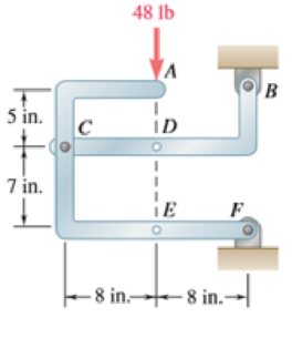
The 48-lb load is removed and a 288-lb · in. clockwise couple is applied successively at A, D, and E. Determine the components of the reactions at Band F if the couple is applied (a) at A, (b) at D, (c) at E.
(a)
The component of reactions at point B and F when the couple is applied at A.
Answer to Problem 6.89P
The x component of the reaction force at point B is
The x component of force applied is
Explanation of Solution
The free body diagram of the problem 6.89P is shown in figure 1 below.
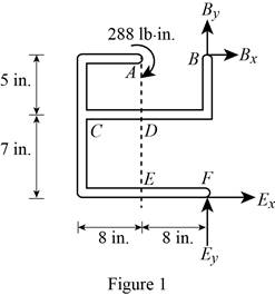
A clockwise couple is applied at A,D, and E. Due to this couple, resultant reaction forces are experienced in points A, D, and E.
First consider the couple applied at point A.
Write the equation to find the sum of moments of force at point F.
Here,
Since the sum of moments of force at a point of a system in equilibrium is zero, rewrite the equation for the sum of moments.
Write the equation to find the x components of force.
Here,
Since the sum of forces at a point is zero in equilibrium, the above equation is rewritten.
Substitute
Write the equation to find the sum of y component of forces.
Here,
No force is applied in the y direction, therefore there will be no reaction also.
Consider figure 2.
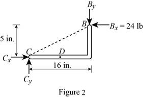
Write the equation to find the y component of reaction force at point B.
Here,
Rewrite equation (I) to find the value of
Conclusion:
Observe figure 2.
Substitute
The y component of reaction force at point B is having a magnitude of
Substitute
The y component of the force applied at point b is
Therefore, the x component of the reaction force at point B is
The x component of force applied is
(b)
The component of reactions at point B and F when the couple is applied at D.
Answer to Problem 6.89P
The x component of the reaction force at point B is
The x component of force applied is
Explanation of Solution
The free body diagram of the problem 6.89P is shown in figure 1.
A clockwise couple is applied at A,D, and E. Due to this couple, resultant reaction forces are experienced in points A, D, and E.
Consider the couple applied at point D.
Write the equation to find the sum of moments of force at point F.
Here,
Since the sum of moments of force at a point of a system in equilibrium is zero, rewrite the equation for the sum of moments.
Write the equation to find the x components of force.
Here,
Since the sum of forces at a point is zero in equilibrium, the above equation is rewritten.
Substitute
Write the equation to find the sum of y component of forces.
Here,
No force is applied in the y direction, therefore there will be no reaction also.
Consider figure 3.
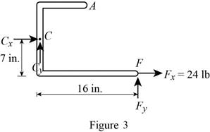
Write the equation to find the y component of reaction force at point B.
Here,
Rewrite equation (I) to find the value of
Conclusion:
Observe figure 3.
Substitute
The y component of force at point B is having a magnitude of
Substitute
The y component of the reaction force applied at point B is
Therefore, the x component of the reaction force at point B is
The x component of force applied is
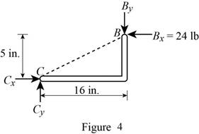
(c)
The component of reactions at point B and F when the couple is applied at E.
Answer to Problem 6.89P
The x component of the reaction force at point B is
The x component of force applied is
Explanation of Solution
The free body diagram of the problem 6.89P is shown in figure 1.
A clockwise couple is applied at A,D, and E. Due to this couple, resultant reaction forces are experienced in points A, D, and E.
First consider the couple applied at point E.
Write the equation to find the sum of moments of force at point F.
Here,
Since the sum of moments of force at a point of a system in equilibrium is zero, rewrite the equation for the sum of moments.
Write the equation to find the x components of force.
Here,
Since the sum of forces at a point is zero in equilibrium, the above equation is rewritten.
Substitute
Write the equation to find the sum of y component of forces.
Here,
No force is applied in the y direction, therefore there will be no reaction also.
Consider figure 4.
Write the equation to find the y component of reaction force at point B.
Here,
Rewrite equation (VII) to find the value of
Conclusion:
Observe figure 4.
Substitute
The y component of reaction force at point B is having a magnitude of
Substitute
The y component of the force applied at point b is
Therefore, the x component of the reaction force at point B is
The x component of force applied is
Want to see more full solutions like this?
Chapter 6 Solutions
Vector Mechanics for Engineers: Statics and Dynamics


- The 80-lb homogeneous plate is supported by a ball-and-socket joint at A, a slider hearing at B, and the cable CE. A 120-lb vertical force is applied to the corner D. Determine the force in the cable and the magnitude of the bearing reaction at B.arrow_forwardThe tow truck’s front wheels will be lifted off the ground if the moment of the load W about the rear axle exceeds the moment of the 2000-kg mass of the truck. Determine the largest W that may be safely applied.arrow_forwardThe 40-ft boom AB weighs 2 kips; the distance from axle A to the center of gravity G of the boom is 20 ft. For the position shown,determine (a) the tension T in the cable, (b) the reaction at A.arrow_forward
- In order to unscrew the tapped faucet A , a plumber uses two pipe wrenches as shown. By exerting a 40-lb force on each wrench at a distance of 10 in. from the axis of the pipe and in a direction perpendicular to the pipe and to the wrench, he prevents the pipe from rotating, and thus he avoids loosening or further tightening the joint between the pipe and the tapped elbow C . Determine (a) the angle 0 that the wrench at A should form with the vertical if elbow C is not to rotate about the vertical, (b) the force-couple system at C equivalent to the two 40-lb forces when this condition is satisfied.arrow_forwardDetermine the components of the reactions at D and E if the frame is loaded by a clockwise couple of magnitude 150 N·m applied (a)at A, (b) at B.arrow_forwardIn order to unscrew the tapped faucet A, a plumber uses two pipe wrenches as shown. By exerting a 40-lb force on each wrench, at a distance of 10 in. from the axis of the pipe and in a direction perpendicular to the pipe and to the wrench, he prevents the pipe from rotating, and thus avoids loosening or further tightening the joint between the pipe and the tapped elbow C. Determine (a) the angle θ that the wrench at A should form with the vertical if elbow C is not to rotate about the vertical, (b) the force-couple system at Cequivalent to the two 40-lb forces when this condition is satisfied.arrow_forward
- A spring of constant 15 kN/m connects points C and F of the linkage shown. Neglecting the weight of the spring and linkage, determine the force in the spring and the vertical motion of point G when a vertical downward 120-N force is applied (a) at point C ,( b) at points C and H.arrow_forwardDetermine the components of the reactions at A and E if the frame is loaded by a clockwise couple of magnitude 36 N.m applied (a) at B, (b) at D.arrow_forwardDetermine the reactions at A and E when the angle α = 30o.arrow_forward
- A 3200-lb forklift truck is used to lift a 1700-lb crate. Determine the reaction at each of the two (a) front wheels A, (b) rear wheels B.arrow_forwardBeam AD carries the two 40-lb loads shown. The beam is held by a fixed support at D and by the cable BE that is attached to the counterweight w . Determine the reaction at D when (a) W = 100 lb, (b) W = 90 lb.arrow_forwardTwo crates, each of mass 350 kg, are placed as shown in the bed of a 1400-kg pick-up truck. Draw the free-body diagram needed to determine the reactions at each of the two rear wheels B.arrow_forward
 International Edition---engineering Mechanics: St...Mechanical EngineeringISBN:9781305501607Author:Andrew Pytel And Jaan KiusalaasPublisher:CENGAGE L