
Concept explainers
Videos
The gears A and D are rigidly attached to horizontal shafts that are held by frictionless bearings. Determine (a) the couple M0 that must be applied to shaft DEF to maintain equilibrium, (b) the reactions at G and H.
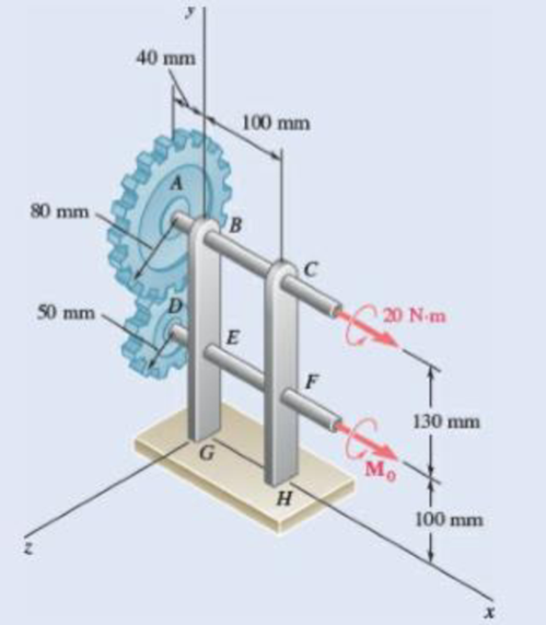
Fig. P6.159
(a)
The couple
Answer to Problem 6.159P
The couple
Explanation of Solution
Take all vectors along the
Radius of gear
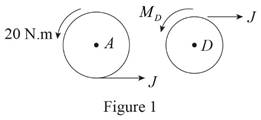
Consider the projection of the gears on
The free body diagram of the Gear
Here,
Write the expression for the moment at
Here,
Above equation implies that net moment at any point is the sum of product of each force acting on the system and perpendicular distance of the force and the point.
The moment at
Thus, write the complete expression of anticlockwise moment
Here,
At equilibrium, the sum of the moment acting at
Write the expression for the total anticlockwise moment acting at
Calculation:
Substitute
Substitute
Since the rotation is in the yz plane , the direction of couple is in
Therefore, the couple
(b)
The reaction at
Answer to Problem 6.159P
The point
Explanation of Solution
Free body diagram of Projection on
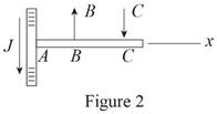
Here, is the tangential force acting on the gear,
From figure 2, write the equation of net moment about
Here,
Above equation implies that net moment at any point is the sum of product of each force acting on the system and perpendicular distance of the force and the point.
The moment at
Thus, write the complete expression of anticlockwise moment
Here,
At equilibrium, the sum of the moment acting at
Write the expression for the total anticlockwise moment acting at
Write the expression for the moment at
Here,
Above equation implies that net moment at any point is the sum of product of each force acting on the system and perpendicular distance of the force and the point.
At equilibrium, the sum of the moment acting at
Write the expression for the total anticlockwise moment acting at
Here,
The free body diagram of the projection on
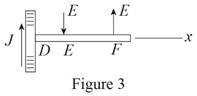
Here,
From figure 3, write the equation of net moment about
Here,
Above equation implies that net moment at any point is the sum of product of each force acting on the system and perpendicular distance of the force and the point.
The moment at
Thus, write the complete expression of anticlockwise moment
Here,
At equilibrium, the sum of the moment acting at
Write the expression for the total anticlockwise moment acting at
Write the expression for the moment at
Here,
Above equation implies that net moment at any point is the sum of product of each force acting on the system and perpendicular distance of the force and the point.
At equilibrium, the sum of the moment acting at
Write the expression for the total anticlockwise moment acting at
Here,
Consider the projection at
The free body diagram of the Bracket
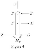
Here,
Write the expression for the total force along
Since in this direction net force is equal to zero. Equate above equation to zero.
Since total moment of force about
Write the equilibrium moment of force about
The free body diagram of the Bracket
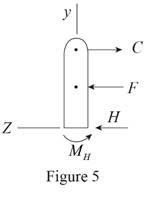
Here,
Write the expression for the total force along
Since in this direction net force is equal to zero. Equate above equation to zero.
Since total moment of force about
Write the equilibrium moment of force about
Calculation:
Substitute
Substitute
Substitute
Substitute
Substitute
Substitute
The negative sign indicate that it is directed along
Substitute
Substitute
The positive value indicate that it is directed along
Substitute
Therefore, the net force at
Want to see more full solutions like this?
Chapter 6 Solutions
Vector Mechanics for Engineers: Statics


- The cab and motor units of the front-end loader shown are connected by a vertical pin located 2 m behind the cab wheels. The distance from C to D is 1 m. The center of gravity of the 300-kN motor unit is located at Gm, while the centers of gravity of the 100-kN cab and 75-kN load are located, respectively, at Gc and Gl. Knowing that the front-end loader is at rest with its brakes released, determine(a) the reactions at each of the four wheels, (b) the forces exertedon the motor unit at C and D.arrow_forwardTwo rods are connected by a frictionless collar B. Knowing that the magnitude of the couple MA is 500 lb·in., determine (a) the couple MC required for equilibrium, (b) the corresponding components of the reaction at C.arrow_forwardTwo transmission belts pass over a double-sheaved pulley that is attached to an axle supported by bearings at A and D . The radius of the inner sheave is 125 mm and the radius of the outer sheave is 250 mm. Knowing that when the system is at rest, the tension is 90 N in both portions of belt B and 150 N in both portions of belt C , determine the reactions at A and D . Assume that the bearing at D does not exert any axial thrust.arrow_forward
- A uniform rod AB of length 2R rests inside a hemispherical bowl of radius R as shown. Neglecting friction, determine the angle 0 corresponding to equilibrium.arrow_forwardTwo tape spools are attached to an axle supported by bearings at A and D . The radius of spool B is 1.5 in. and the radius of spool C is 2 in. Knowing that TB= 20 lb and that the system rotates at a constant rate, draw the free-body diagram needed to determine the reactions at A and D . Assume that the bearing at A does not exert any axial thrust and neglect the weights of the spools and axle.arrow_forwardArm ABC is connected by pins to a collar at B and to crank CD at C Neglecting the effect of friction, determine the couple M required to hold the system in equilibrium 'when 0= 0.Fig.P6.133arrow_forward
- Knowing that for the rod of Prob. 4.89, L = 15 in., R = 20 in., and W = 10 lb, determine (a) the angle 0 corresponding to equilibrium, (b) the reactions at A and B.(Reference to Problem 4.89):A slender rod with a length of L and weight W is attached to a collar at A and is fitted with a small wheel at B . Knowing that the wheel rolls freely along a cylindrical surface of radius R , and neglecting friction, derive an equation in 0, L, and that must be satisfied when the rod is in equilibrium.arrow_forwardThe T-shaped bracket shown is supported by a small wheel at E and pegs at C and D . Neglecting the effect of friction, determine the reactions at C, D, and E when 0= 30°.arrow_forward4.7 A hand truck is used to move a compressed-air cylinder. Knowing that the combined weight of the truck and cylinder is 180 lb. determine (a) the vertical force P that should be applied to the handle to maintain the cylinder in the position shown, (b) the corresponding reaction at each of the two wheels.arrow_forward
- Two 9-in.-diameter pipes (pipe 1 and pipe 2) are supported every 7.5 ft by a small frame like that shown. Knowing that the combined weight of each pipe and its contents is 30 lb/ft and assuming frictionless surfaces, determine the components of the reactions at A and G.arrow_forwardThe 10-lb bar AE is suspended by a cable that passes over a 5-in.-radius drum. Vertical motion of end E of the bar is prevented by the two stops shown. Knowing that μs= 0.30 between the cable and the drum, determine (a) the largest counterclockwise couple M0 that can be applied to the drum if slipping is not to occur, (b) the corresponding force exerted on end E of the bar.arrow_forwardAn 8-kg slender rod of length L is attached to collars that can slide freely along the guides shown. Knowing that the rod is in equilibrium and that β= 30°, determine (a) the angle 0 that the rod forms with the vertical, (b) the reactions at A and B.arrow_forward
 Elements Of ElectromagneticsMechanical EngineeringISBN:9780190698614Author:Sadiku, Matthew N. O.Publisher:Oxford University Press
 Mechanics of Materials (10th Edition)Mechanical EngineeringISBN:9780134319650Author:Russell C. HibbelerPublisher:PEARSON
 Thermodynamics: An Engineering ApproachMechanical EngineeringISBN:9781259822674Author:Yunus A. Cengel Dr., Michael A. BolesPublisher:McGraw-Hill Education
 Control Systems EngineeringMechanical EngineeringISBN:9781118170519Author:Norman S. NisePublisher:WILEY
 Mechanics of Materials (MindTap Course List)Mechanical EngineeringISBN:9781337093347Author:Barry J. Goodno, James M. GerePublisher:Cengage Learning
 Engineering Mechanics: StaticsMechanical EngineeringISBN:9781118807330Author:James L. Meriam, L. G. Kraige, J. N. BoltonPublisher:WILEY