
Concept explainers
Videos
6.56 and 6.57 A composite beam is made by attaching the timber and steel portions shown with bolts of 12-mm diameter spaced longitudinally every 200 mm. The modulus of elasticity is 10 GPa for the wood and 200 GPa for the steel. For a vertical shear of 4 kN, determine (a) the average shearing stress in the bolts, (b) the shearing stress at the center of the cross section. (Hint: Use the method indicated in Prob. 6.55.)
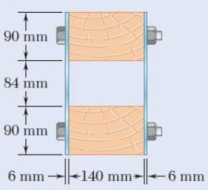
Fig. p6.56
(a)
The average shearing stress in the bolts.
Answer to Problem 56P
The average shearing stress in the bolts is
Explanation of Solution
Given information:
The diameter of the bolts is
The longitudinal spacing is
The beam is subjected to a vertical shear of
The modulus of elasticity for wood
The modulus of elasticity for steel
Calculation:
Consider the steel is to be the reference material. So modular ratio of steel is
Calculate the modular ratio of timber wood
Here,
Substitute
Total depth of the section d is as follows:
Calculate the moment of inertia for the symmetric section I as shown below.
Here, b is the width of the section and d is the depth of the section.
For steel:
For wood:
Calculate the moment of inertia for the transformed section as shown below.
Substitute 1 for
Calculate the first moment of area as shown below.
For wooden section:
Calculate the first moment of area for the transformed section Q as shown below.
Substitute
Calculate the horizontal shear per unit length q as shown below.
Here V is the vertical shear.
Substitute
Calculate the force acting on the bolt
Here, s is the longitudinal spacing.
Substitute
Calculate the area of bolt
Here,
Substitute
The bolt is subjected to double shear.
Calculate the shearing stress of the bolt
Substitute
Therefore, the average shearing stress in the bolts is
(b)
The shearing stress at the center of the cross section.
Answer to Problem 56P
The shearing stress at the center of the cross section is
Explanation of Solution
Given information:
The diameter of the bolts is
The longitudinal spacing is
The beam is subjected to a vertical shear of
The modulus of elasticity for wood
The modulus of elasticity for steel
Calculation:
Refer to part (a).
Moment of inertia for the transformed section
Calculate the first moment of area as shown below.
For the two steel plates:
Calculate the first moment of area along the neutral axis for the transformed section as shown below.
Substitute
Calculate the horizontal shear per unit length as shown below.
Substitute
Calculate the shearing stress as shown below.
Substitute
Therefore, the shearing stress at the center of the cross section is
Want to see more full solutions like this?
Chapter 6 Solutions
Mechanics of Materials, 7th Edition


- A square box beam is made of two 20 x 80-mm planks and two 20 x 120-mm planks nailed together as shown. Knowing that the spacing between the nails is s= 30 mm and that the vertical shear in the beam is V=1200 N, determine (a) the shearing force in each nail, (b) the maximum shearing stress in the beam.arrow_forwardtwo 20 x 100-mm and two 20 x 180 mm boards are glued together as shown to form a 120 x 200 mm box beam. Knowing that the beams are subjected to a vertical shear of 3.625 kN. Determin the average shearing stress in the glued joint at Barrow_forwardTwo W8 x 31 rolled sections can be welded at A and B in either of the two ways shown in order to form a composite beam. Knowing that for each weld the allowable horizontal shearing force is 3000 lb per inch of weld, determine the maximum allowable vertical shear in the composite beam for each of the two arrangements shown.arrow_forward
- Three 1 x 18-in. steel plates are bolted to four L6 x 6 x 1 angles to form a beam with the cross section shown. The bolts have a 78-in. diameter and are spaced longitudinally every 5 in. Knowing that the allowable average shearing stress in the bolts is 12 ksi, determine the largest permissible vertical shear in the beam. (Given: Ix= 6123 in4.)arrow_forwardThe wooden members A and B are to be joined by plywood splice plates that will be fully glued on the surfaces in contact. As part of the design of the joint, and knowing that the clearance between the ends of the members is to be 8 mm, determine the smallest allowable length L if the average shearing stress in the glue is not to exceed 800 kPa.arrow_forwardThe composite beam shown is fabricated by connecting two W6 *20 rolled-steel members, using bolts of 5/8-in. diameter spaced longitudi-nally every 6 in. Knowing that the average allowable shearing stress in the bolts is 10.5 ksi, determine the largest allowable vertical shear in the beam.arrow_forward
- The built-up timber beam is subjected to a vertical shear of 1200 lb.Knowing that the allowable shearing force in the nails is 75 lb, determine the largest permissible spacing s of the nails.arrow_forwardTwo 20 × 100-mm and two 20 × 180-mm boards are glued together as shown to form a 120 × 200-mm box beam. Know that the beam is subjected to a vertical shear of 3.625 kN. Determine the average shearing stress in the glued joint at B.arrow_forwardAn extruded beam has the cross section shown and a uniform wall thickness of 0.20 in. Knowing that a given vertical shear V causes a maximum shearing stress τ= 9 ksi, determine the shearing stress at the four points indicated. assuming that the beam is subjected to a horizontal shear Varrow_forward
- The thin-walled extruded beam shown is made of aluminum and has a uni-form 3-mm wall thickness. Knowing that the shear in the beam is 5 kN, deter-mine (a) the shearing stress at point A, (b) the maximum shearing stress in the beam. Note: The dimensions given are to lines midway between the outer and inner surfaces of the beam.arrow_forwardLink AB, of width b = 50 mm and thickness t = 6 mm, is used to support the end of a horizontal beam. Knowing that the average normal stress in the link is –140 MPa, and that the average shearing stress in each of the two pins is 80 MPa, determine (a) the diameter d of the pins, (b) the average bearing stress in the link.arrow_forwardShaft BC is hollow with inner and outer diameters of 90 mm and 120 mm, respectively. Shafts AB and CD are solid and of diameter d. For the loading shown, determine (a) the maximum and minimum shearing stress in shaft BC, (b) the required diameter d of shafts AB and CD if the allowable shear-ing stress in these shafts is 65 MPa.arrow_forward
 Elements Of ElectromagneticsMechanical EngineeringISBN:9780190698614Author:Sadiku, Matthew N. O.Publisher:Oxford University Press
 Mechanics of Materials (10th Edition)Mechanical EngineeringISBN:9780134319650Author:Russell C. HibbelerPublisher:PEARSON
 Thermodynamics: An Engineering ApproachMechanical EngineeringISBN:9781259822674Author:Yunus A. Cengel Dr., Michael A. BolesPublisher:McGraw-Hill Education
 Control Systems EngineeringMechanical EngineeringISBN:9781118170519Author:Norman S. NisePublisher:WILEY
 Mechanics of Materials (MindTap Course List)Mechanical EngineeringISBN:9781337093347Author:Barry J. Goodno, James M. GerePublisher:Cengage Learning
 Engineering Mechanics: StaticsMechanical EngineeringISBN:9781118807330Author:James L. Meriam, L. G. Kraige, J. N. BoltonPublisher:WILEY