
Videos
6.65 through 6.68 An extruded beam has the cross section shown. Determine (a) the location of the shear center O, (b) the distribution of the shearing stresses caused by the vertical shearing force V shown applied at O.
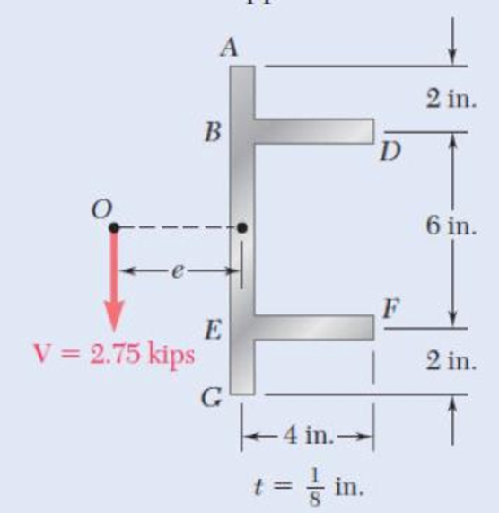
Fig. p6.67
(a)
Find the location of the shear center O.
Answer to Problem 68P
The location of the shear center O is
Explanation of Solution
Calculation:
Calculate the moment of inertia as shown below.
Here, b is the width of the section, d is the height of the section, A is the area of the beam, and
Calculate the moment of inertia for whole section as shown below.
Calculate the forces acting along the member as shown below.
Here,
Sketch the cross section of flange as shown in Figure 1.
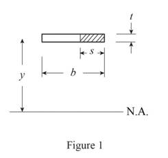
Refer to Figure 1.
Calculate the first moment of area as shown below.
Calculate the first moment of area for AB as shown below.
Calculate the horizontal shear per unit length as shown below.
Here, V is the vertical shear.
Substitute
Calculate the force
Substitute
For flange AB and flange HJ:
Substitute
For flange DE and flange FG:
Substitute
Sketch the shear flow as shown in Figure 2.
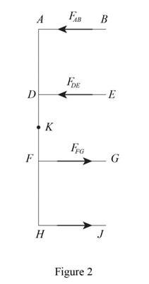
Refer to Figure 2.
Calculate the eccentricity as shown below.
Substitute
Therefore, the location of the shear center O is
(b)
Find the distribution of the shearing stresses caused by the vertical shearing force.
Answer to Problem 68P
The shearing stress at point B, E, G, and J is
The shearing stress at point A and H is
The shearing stress at point just above D and just below F is
The shearing stress at point just to the right of D and just to the right of F is
The shearing stress at point just below D and just above F is
The shearing stress at point K is
Explanation of Solution
Given information:
The vertical shear is
Calculation:
Refer to part (a).
The moment of inertia
Calculate the shear stress as shown below.
At point B, E, G, and J:
Calculate the first moment of area as shown below.
Hence, the shearing stress at point B, E, G, and J is
At point A and H:
Calculate the first moment of area as shown below.
The thickness of the section is
Calculate the shear stress as shown below.
Substitute
Hence, the shearing stress at point A and H is
At point just above D and just below F:
Calculate the first moment of area as shown below.
The thickness of the section is
Calculate the shear stress as shown below.
Substitute
Hence, the shearing stress at point just above D and just below F is
At point just to the right of D and just to the right of F:
Calculate the first moment of area as shown below.
The thickness of the section is
Calculate the shear stress as shown below.
Substitute
Hence, the shearing stress at point just to the right of D and just to the right of F is
At point just below D and just above F:
Calculate the first moment of area as shown below.
The thickness of the section is
Calculate the shear stress as shown below.
Substitute
Hence, the shearing stress at point just below D and just above F is
At point just below D and just above F:
Calculate the first moment of area as shown below.
The thickness of the section is
Calculate the shear stress as shown below.
Substitute
Hence, the shearing stress at point just below D and just above F is
At point K:
Calculate the first moment of area as shown below.
The thickness of the section is
Calculate the shear stress as shown below.
Substitute
Therefore, the shearing stress at point K is
Want to see more full solutions like this?
Chapter 6 Solutions
Mechanics of Materials, 7th Edition


- A cable AB of span L and a simple beam A'B' of the same span are subjected to identical vertical loadings as shown. Show that the magnitude of the bending moment at a point C' in the beam is equal to the product T0h, where T0 is the magnitude of the horizontal component of the tension force in the cable and h is the vertical distance between point C and the chord joining the points of support A and B.arrow_forwardThe American Standard rolled-steel beam shown has been reinforced by attaching to it two 16 x 200-mm plates, using 18-mm-diameter bolts spaced longitudinally every 120 mm. Knowing that the average allowable shearing stress in the bolts is 90 MPa, determine the largest permissible vertical shearing force.arrow_forwardA beam consists of three planks connected by steel bolts with a lon-gitudinal spacing of 225 mm. Knowing that the shear in the beam is vertical and equal to 6 kN and that the allowable average shearing stress in each bolt is 60 MPa, determine the smallest permissible bolt diameter that can be usedarrow_forward
- For the wide-flange beam with the loading shown, determine the largest load P that can be applied, knowing that the maximum normal stress is 160 MPa and the largest shearing stress is 100 MPa. W360 x 122 Barrow_forwardKnowing that P= 480 N,Q=320N determine (a) the distance a for which the absolute value of the bending moment in the beam is as small as possible, (b) the corresponding maximum normal stress due to bending.arrow_forwardFour L102 x 102 x 9.5 steel angle shapes and a 12 x 400-mm steel plate are bolted together to form a beam with the cross section shown. The bolts are of 22-mm diameter and are spaced longitudinally every 120 mm. Knowing that the beam is subjected to a vertical shear of 240 kN, determine the average shearing stress in each bolt.arrow_forward
- An elastomeric bearing (G=130 psi) is used to support a bridge girder as shown to provide flexibility during earthquakes. The beam must not displace more than 38 in. when a 5-kip lateral load is applied as shown. Knowing that the maximum allowable shearing stress is 60 psi, determine (a) the smallest allowable dimension b, (b) the smallest required thickness a.arrow_forwardA square box beam is made of two 20 x 80-mm planks and two 20 x 120-mm planks nailed together as shown. Knowing that the spacing between the nails is s= 30 mm and that the vertical shear in the beam is V=1200 N, determine (a) the shearing force in each nail, (b) the maximum shearing stress in the beam.arrow_forwardThree boards, each of 1.5 x3.5-in. rectangular cross section, are nailed together to form a beam that is subjected to a vertical shear of 250 lb. Knowing that the spacing between each pair of nails is 2.5 in., determine the shearing force in each nail.arrow_forward
- A) The four cross sections shown have different characteristics when subjected to a vertical shear force. Which of the four geometries shown has the largest value for the moment of the area, Q, about the neutral axis? B) Which of the four geometries shown has the smallest value for its moment of inertia about the x axis? C) Given that all four geometries are subjected to the same vertical shear force V, which of the four has the smallest value for the maximum shear stress?arrow_forwardThree 1 x 18-in. steel plates are bolted to four L6 x 6 x 1 angles to form a beam with the cross section shown. The bolts have a 78-in. diameter and are spaced longitudinally every 5 in. Knowing that the allowable average shearing stress in the bolts is 12 ksi, determine the largest permissible vertical shear in the beam. (Given: Ix= 6123 in4.)arrow_forwardA milling operation was used to remove a portion of a solid bar of square cross section. Knowing that a= 30 mm, d= 20 mm, and σall= 60 MPa, determine the magnitude P of the largest forces that can be safely applied at the centers of the ends of the bar.arrow_forward
 Elements Of ElectromagneticsMechanical EngineeringISBN:9780190698614Author:Sadiku, Matthew N. O.Publisher:Oxford University Press
 Mechanics of Materials (10th Edition)Mechanical EngineeringISBN:9780134319650Author:Russell C. HibbelerPublisher:PEARSON
 Thermodynamics: An Engineering ApproachMechanical EngineeringISBN:9781259822674Author:Yunus A. Cengel Dr., Michael A. BolesPublisher:McGraw-Hill Education
 Control Systems EngineeringMechanical EngineeringISBN:9781118170519Author:Norman S. NisePublisher:WILEY
 Mechanics of Materials (MindTap Course List)Mechanical EngineeringISBN:9781337093347Author:Barry J. Goodno, James M. GerePublisher:Cengage Learning
 Engineering Mechanics: StaticsMechanical EngineeringISBN:9781118807330Author:James L. Meriam, L. G. Kraige, J. N. BoltonPublisher:WILEY