
Concept explainers
Videos
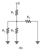
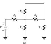
Which elements (individual elements, not combinations of elements) of the networks in Fig. 7.64. are in series? Which are in parallel? As a check on your assumptions, be sure that the elements in series have the same current and that the elements in parallel have the same voltage. Restrict your decisions to single elements not combinations of elements.
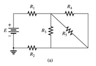
Fig 7.64
(a)
The elements of the network that are in series and in parallel.
Answer to Problem 1P
Explanation of Solution
Given:
A network is given as below.
Concept Used:
Elements in the series have the same current.
Elements in the parallels have the same voltage.
Calculation:
A network is given as below.

Since same current is flowing through
So,
Also, since same voltage is flowing through
So,
Conclusion:
Hence,
(b)
The elements of the network that are in series and in parallel.
Answer to Problem 1P
Explanation of Solution
Given:
A network is given as below.
Concept Used:
Elements in the series have the same current.
Elements in the parallels have the same voltage.
Calculation:
A network is given as below.

Since same current is flowing through
So,
And since same voltage is flowing through
So,
Conclusion:
Hence,
(c)
The elements of the network that are in series and in parallel.
Answer to Problem 1P
Explanation of Solution
Given:
A network is given as below.
Concept Used:
Elements in the series have the same current.
Elements in the parallels have the same voltage.
Calculation:
A network is given as below.

Since same current is flowing through
So,
Since same voltage is across
So,
Conclusion:
Hence,
Want to see more full solutions like this?
Chapter 7 Solutions
Introductory Circuit Analysis; Laboratory Manual For Introductory Circuit Analysis Format: Kit/package/shrinkwrap
Additional Engineering Textbook Solutions
Fundamentals of Applied Electromagnetics (7th Edition)
Electrical Engineering: Principles & Applications (7th Edition)
Computer Systems: A Programmer's Perspective (3rd Edition)
Starting Out with Java: From Control Structures through Data Structures (3rd Edition)
Starting Out with Java: From Control Structures through Data Structures (4th Edition) (What's New in Computer Science)
C Programming Language


- Determine IDQ for the network of Fig. 7.80 using a purely mathematical approacHarrow_forwardFor the ladder network in fig . 7.90 A. Find the current I B.Find the current I7 C.determine the voltage V3 V5 and V7 D. Calculate the power delivered to R7 and compare it to the power delivered by the 240 V supplyarrow_forwardThe switch in the circuit seen in fig 7.54arrow_forward
- The system of using helicopters to work on live power lines is based on the principle that electrical current seeks to flow into the ground. Select one: True Falsearrow_forward7 Renewable Energy Sources are readily available everywhere, whole year round. Select one: True Falsearrow_forward7. The longer the length of the arc, the higher will be the Arc Resistance. Select one: True Falsearrow_forward
- A two-story house with a full basement has an outside dimension of 7.3 m (24 f) by 9.1 m (30 ft). Assuming three appliance circuits, determine the total load and the total demand load. Determine the wind power of a wind turbine travelling the speed of 36km/hr and has a blade length of 3000mm.arrow_forwardQuestion 7.31 For the network of Fig. 7.105, determine:a. IDQ and VGSQ.b.VDS.c. VD. .arrow_forwardGiven VDS = 4 V for the network of Fig. 7.89, determine: a. IDb. VD and VS c. VGarrow_forward
- A 7 year’s old little boy “Ahmad Salar” uses his father’s mobile phone. He installs games from the Google Play store quite often. However, being a probing guy he sometimes gets curious that while he is in process of installing a certain game he cannot instantiate another process of the game. Ahmed asked his father about the dilemma. The father took a scientific approach to answer the question. The answer was something to do with Software patterns. Your task is to identify the precise pattern and logically argue about its intent and usefulness. Draw a UML diagram for the identified pattern also.arrow_forwardQuestion 7.11 Find VS for the network of Fig. 7.89.arrow_forwardPlease provide solution and show the complete answerarrow_forward
 Introductory Circuit Analysis (13th Edition)Electrical EngineeringISBN:9780133923605Author:Robert L. BoylestadPublisher:PEARSON
 Delmar's Standard Textbook Of ElectricityElectrical EngineeringISBN:9781337900348Author:Stephen L. HermanPublisher:Cengage Learning
 Programmable Logic ControllersElectrical EngineeringISBN:9780073373843Author:Frank D. PetruzellaPublisher:McGraw-Hill Education
 Fundamentals of Electric CircuitsElectrical EngineeringISBN:9780078028229Author:Charles K Alexander, Matthew SadikuPublisher:McGraw-Hill Education
 Electric Circuits. (11th Edition)Electrical EngineeringISBN:9780134746968Author:James W. Nilsson, Susan RiedelPublisher:PEARSON
 Engineering ElectromagneticsElectrical EngineeringISBN:9780078028151Author:Hayt, William H. (william Hart), Jr, BUCK, John A.Publisher:Mcgraw-hill Education,