Fundamentals of Electric Circuits
6th Edition
ISBN: 9780078028229
Author: Charles K Alexander, Matthew Sadiku
Publisher: McGraw-Hill Education
bartleby

Concept explainers

bartleby

Videos

Textbook Question
Book Icon
Chapter 7, Problem 50P

In the circuit of Fig. 7.117, find ix for t > 0. Let R1 = R2 = 1 kΩ, R3 = 2 kΩ, and C = 0.25 mF.
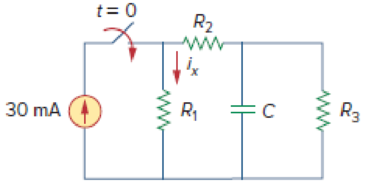
Chapter 7, Problem 50P, In the circuit of Fig. 7.117, find ix for t  0. Let R1 = R2 = 1 k, R3 = 2 k, and C = 0.25 mF. Figure

Figure 7.117

Expert Solution & Answer
Check Mark
To determine

Calculate the current ix through the resistance R1 for t>0 in the given circuit of Figure 7.117.

Answer to Problem 50P

The current ix through the resistance R1 is 7.5(3e4t)mA for t>0.

Explanation of Solution

Given data:

Refer to Figure 7.117 in the textbook.

The source current (is) is 30mA

The value of resistances are R1=R2=1kΩ and R3=2kΩ.

The value of capacitance (C) is 0.25mF.

Formula used:

Write the general expression to find the complete voltage response for an RC circuit.

v(t)=v()+[v(0)v()]etτ (1)

Here,

τ is the time constant for the RC circuit,

v(0) is the initial capacitor voltage, and

v() is the final capacitor voltage.

Write the expression to find the time constant for an RC circuit.

τ=RThC (2)

Here,

RTh is the Thevenin resistance, and

C is the capacitance of the capacitor.

Calculation:

The given Figure 7.117 is redrawn as shown in Figure 1.
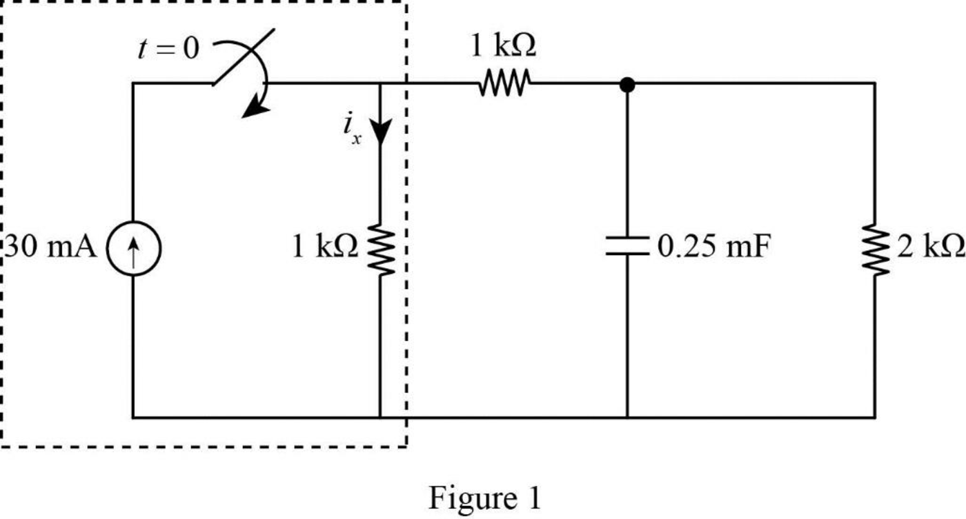
Fundamentals of Electric Circuits, Chapter 7, Problem 50P , additional homework tip  1

For t<0:

The switch is kept open at this condition. Therefore, the initial capacitor voltage v(0) is equal to zero. That is,

v(0)=0V

For t>0:

In Figure 1, the current source 30mA with parallel resistance R1=1kΩ is transformed into voltage source with series resistance R1=1kΩ using source transformation.

That is,

V=(30mA)(1kΩ)=(30×103A)(1×10³Ω){1m=103,1k=103}=30V{1V=1A1Ω}

Figure 2 shows the modified circuit diagram when t>0.

Fundamentals of Electric Circuits, Chapter 7, Problem 50P , additional homework tip  2

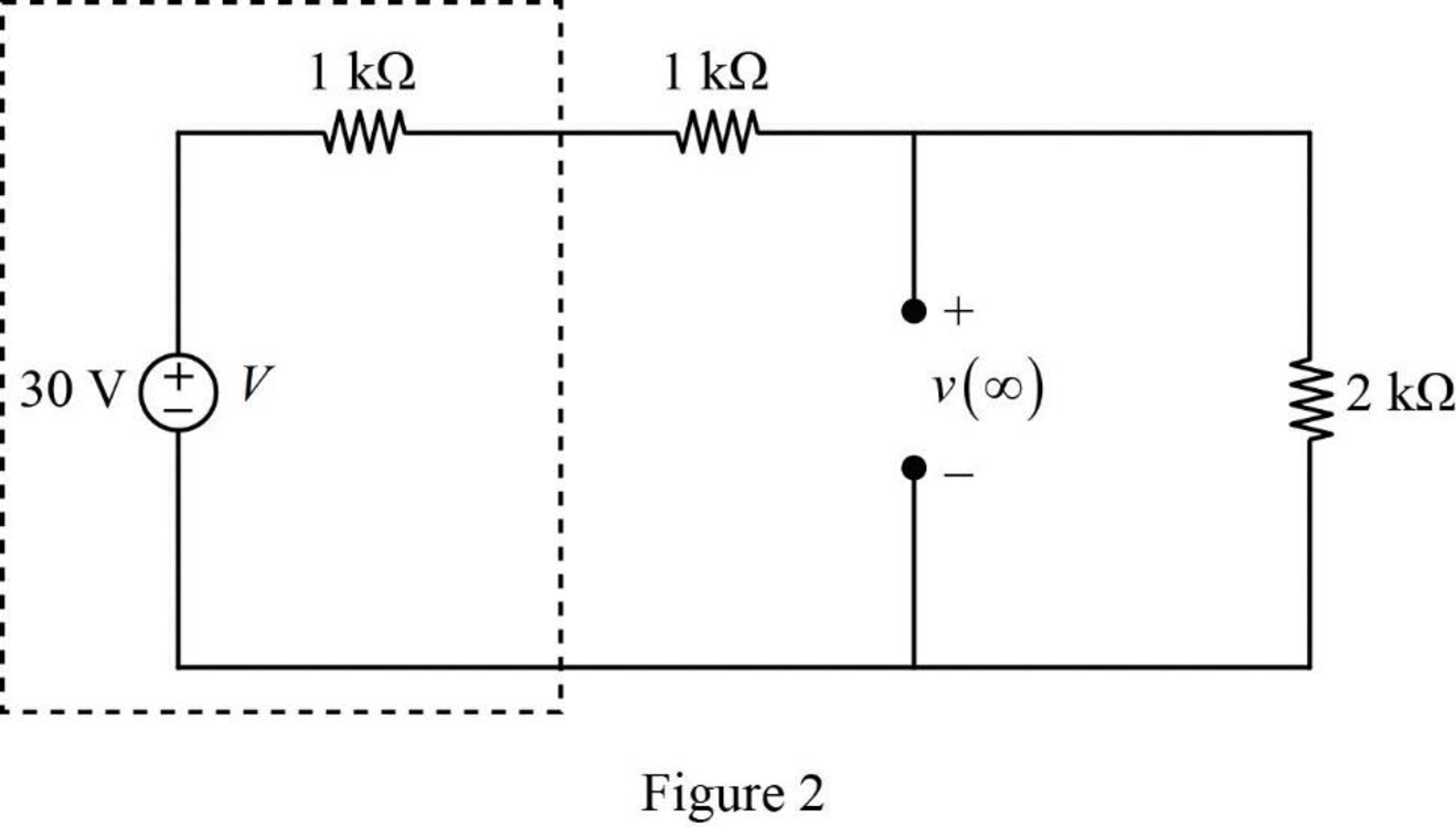
In Figure 2, the final capacitor voltage v() is calculated by using voltage division rule.

v()=(30V)(2kΩ1kΩ+1kΩ+2kΩ)=(30V)(24)=15V

Figure 2 shows the Thevenin resistance RTh at the capacitor terminal.

Fundamentals of Electric Circuits, Chapter 7, Problem 50P , additional homework tip  3

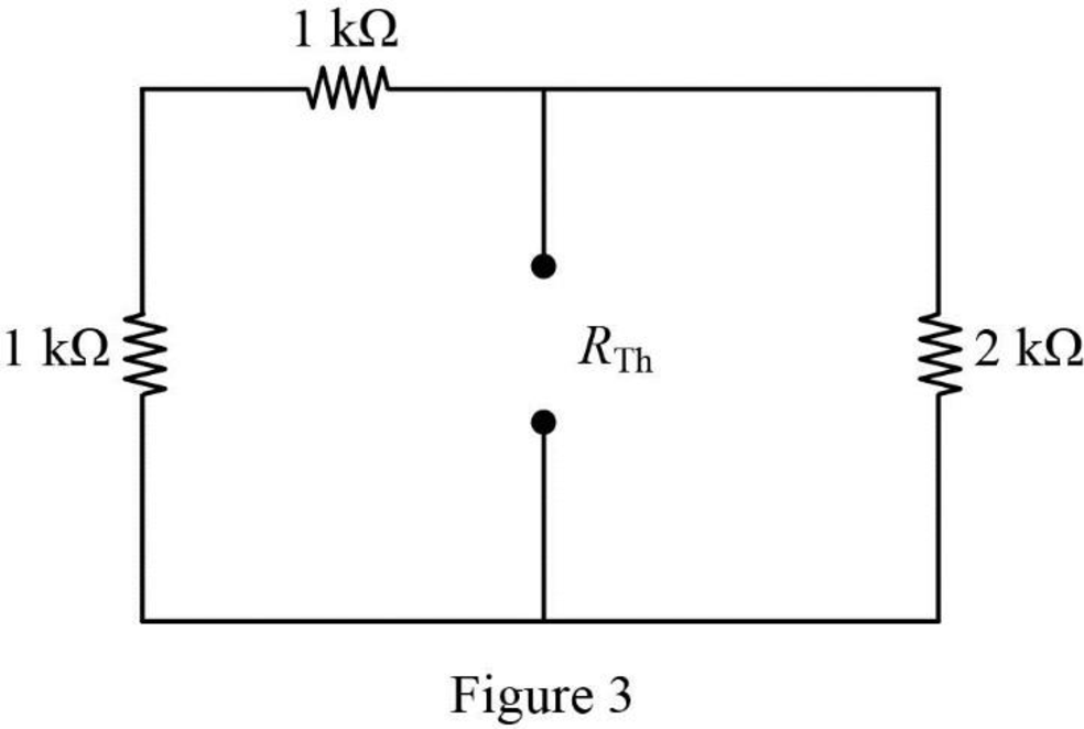
In Figure 3, the Thevenin resistance is calculated as follows.

RTh=(1kΩ+1kΩ)||2kΩ=2kΩ||2kΩ=2kΩ×2kΩ2kΩ+2kΩ=1kΩ

Substitute 1kΩ for RTh and 0.25mF for C in equation (2) to find the time constant τ.

τ=(1kΩ)(0.25mF)

τ=(1×10³Ω)(0.25×10³F){1m=103,1k=103} (3)

Substitute the units VA for Ω and AsV for F in equation (3) to find the time constant τ in seconds.

τ=(1×10³VA)(0.25×10³AsV)=0.25s

Substitute 0V for v(0), 15V for v(), and 0.25s for τ in equation (1) to find the output voltage across the capacitor v(t) in volts.

v(t)=15V+[0V15V]et0.25s=15V[15V]e4t

v(t)=15(1e4t)V (4)

Figure 4 shows the modified circuit diagram to find the current ix.

Fundamentals of Electric Circuits, Chapter 7, Problem 50P , additional homework tip  4

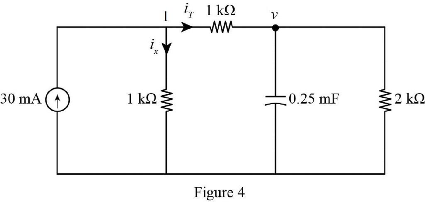
In Figure 4, apply Kirchhoff’s current law at node 1.

ix=30mAiT (5)

In Figure 4, apply Kirchhoff’s current law at node v.

iT=vR3+Cdvdt (6)

Substitute 15(1e4t)V for v, 2kΩ for R3, 0.25mF for C in equation (6) to find the current iT in amperes.

iT=15(1e4t)V2kΩ+(0.25mF)ddt(15(1e4t)V)=15(1e4t)V2×103Ω+(0.25×10³F)ddt(15(1e4t)V){1m=103,1k=103}=15(1e4t)V2×103Ω+(0.25×10³F)(15(0(4)e4t)Vs)=7.5×10³(1e4t)A+(0.25×10³F)(60e4tVs){1A=1V1Ω}

Reduce the equation as follows,

iT=7.5×10³(1e4t)A+(0.25×10³AsV)(60e4tVs){1F=1A1sV}=7.5×10³A7.5×103e4tA+15×103e4tA=7.5×10³A+7.5×10³e4tA

Substitute 7.5×10³A+7.5×10³e4tA for iT in equation (5) to find the current ix in amperes.

ix=30mA(7.5×10³A+7.5×10³e4tA)=30mA7.5×103A7.5×103e4tA=30mA7.5mA7.5e4tmA{1m=103}=22.5mA7.5e4tmA

Reduce the equation as follows,

ix=(22.57.5e4t)mA=7.5(3e4t)mA

Conclusion:

Thus, the current ix through the resistance R1 is 7.5(3e4t)mA for t>0.

Want to see more full solutions like this?

Subscribe now to access step-by-step solutions to millions of textbook problems written by subject matter experts!
Students have asked these similar questions
The switch in the circuit shown in Fig. 7.21 has been in position a for a longtime. At t=0, the switch moves from position a to position b. The switch is amake-before-break type; that is, the connection at position b is establishedbefore the connection at position a is broken, so the inductor current iscontinuous.5. Plot both i(t) and v(t) versus t.
The switch in the circuit shown in Fig. 7.6 has been closed for a long timebefore it is opened at t=0. Find 4. the percentage of the total energy stored in the 2 H inductor that isdissipated in the 10 Ω resistor.
7.4 The switch in the circuit shown has been closed for a long timebefore being opened at t=0.1. a) Find vo(t) for t≥0.

Chapter 7 Solutions

Fundamentals of Electric Circuits

Ch. 7.5 - The switch in Fig. 7.47 is closed at t = 0. Find...Ch. 7.6 - The switch in Fig. 7.52 has been closed for a long...Ch. 7.6 - Switch S1 in Fig. 7.54 is closed at t = 0, and...Ch. 7.7 - For the op amp circuit in Fig. 7.56, find vo for t...Ch. 7.7 - Find v(t) and vo(t) in the op amp circuit of Fig....Ch. 7.7 - Obtain the step response vo(t) for the circuit in...Ch. 7.8 - For the circuit in Fig. 7.66, use Pspice to find...Ch. 7.8 - The switch in Fig. 7.71 was open for a long time...Ch. 7.9 - The RC circuit in Fig. 7.74 is designed to operate...Ch. 7.9 - The flash unit of a camera has a 2-mF capacitor...Ch. 7.9 - A relay has a resistance of 200 and an inductance...Ch. 7.9 - Prob. 22PPCh. 7 - An RC circuit has R = 2 and C = 4 F. The time...Ch. 7 - The time constant for an RL circuit with R = 2 ...Ch. 7 - A capacitor in an RC circuit with R = 2 and C = 4...Ch. 7 - An RL circuit has R = 2 and L = 4 H. The time...Ch. 7 - In the circuit of Fig. 7.79, the capacitor voltage...Ch. 7 - Figure 7.79 For Review Questions 7.5 and 7.6....Ch. 7 - For the circuit in Fig. 7.80, the inductor current...Ch. 7 - Figure 7.80 For Review Questions 7.7 and 7.8....Ch. 7 - If vs changes from 2 V to 4 V at t = 0, we may...Ch. 7 - The pulse in Fig. 7.116(a) can be expressed in...Ch. 7 - In the circuit shown in Fig. 7.81...Ch. 7 - Find the time constant for the RC circuit in Fig....Ch. 7 - Determine the time constant for the circuit in...Ch. 7 - The switch in Fig. 7.84 has been in position A for...Ch. 7 - Using Fig. 7.85, design a problem to help other...Ch. 7 - The switch in Fig. 7.86 has been closed for a long...Ch. 7 - Assuming that the switch in Fig. 7.87 has been in...Ch. 7 - For the circuit in Fig. 7.88, if...Ch. 7 - The switch in Fig. 7.89 opens at t = 0. Find vo...Ch. 7 - For the circuit in Fig. 7.90, find vo(t) for t 0....Ch. 7 - For the circuit in Fig. 7.91, find io for t 0....Ch. 7 - Using Fig. 7.92, design a problem to help other...Ch. 7 - In the circuit of Fig. 7.93,...Ch. 7 - Calculate the time constant of the circuit in Fig....Ch. 7 - Find the time constant for each of the circuits in...Ch. 7 - Determine the time constant for each of the...Ch. 7 - Consider the circuit of Fig. 7.97. Find vo(t) if...Ch. 7 - For the circuit in Fig. 7.98, determine vo(t) when...Ch. 7 - In the circuit of Fig. 7.99, find i(t) for t 0 if...Ch. 7 - For the circuit in Fig. 7.100, v = 90e50t V and i...Ch. 7 - In the circuit of Fig. 7.101, find the value of R...Ch. 7 - Find i(t) and v(t) for t 0 in the circuit of Fig....Ch. 7 - Consider the circuit in Fig. 7.103. Given that...Ch. 7 - Express the following signals in terms of...Ch. 7 - Design a problem to help other students better...Ch. 7 - Express the signals in Fig. 7.104 in terms of...Ch. 7 - Express v(t) in Fig. 7.105 in terms of step...Ch. 7 - Sketch the waveform represented by i(t) = [r(t) ...Ch. 7 - Sketch the following functions: (a) x(t) = 10etu(t...Ch. 7 - Prob. 30PCh. 7 - Evaluate the following integrals: (a)e4t2(t2)dt...Ch. 7 - Prob. 32PCh. 7 - The voltage across a 10-mH inductor is 45(t 2)mV....Ch. 7 - Evaluate the following derivatives: (a) ddtut1ut+1...Ch. 7 - Find the solution to the following differential...Ch. 7 - Solve for v in the following differential...Ch. 7 - A circuit is described by 4dvdt+v=10 (a) What is...Ch. 7 - A circuit is described by didt+3i=2ut Find i(t)...Ch. 7 - Calculate the capacitor voltage for t 0 and t 0...Ch. 7 - Find the capacitor voltage for t 0 and t 0 for...Ch. 7 - Using Fig. 7.108, design a problem to help other...Ch. 7 - (a) If the switch in Fig. 7.109 has been open for...Ch. 7 - Consider the circuit in Fig. 7.110. Find i(t) for...Ch. 7 - The switch in Fig. 7.111 has been in position a...Ch. 7 - Find vo in the circuit of Fig. 7.112 when vs =...Ch. 7 - Prob. 46PCh. 7 - Determine v(t) for t 0 in the circuit of Fig....Ch. 7 - Find v(t) and i(t) in the circuit of Fig. 7.115....Ch. 7 - If the waveform in Fig. 7.116(a) is applied to the...Ch. 7 - In the circuit of Fig. 7.117, find ix for t 0....Ch. 7 - Rather than applying the shortcut technique used...Ch. 7 - Using Fig. 7.118, design a problem to help other...Ch. 7 - Determine the inductor current i(t) for both t 0...Ch. 7 - Obtain the inductor current for both t 0 and t 0...Ch. 7 - Find v(t) for t 0 and t 0 in the circuit of Fig....Ch. 7 - Prob. 56PCh. 7 - Prob. 57PCh. 7 - Rework Prob. 7.17 if i(0) = 10 A and v(t) = 20u(t)...Ch. 7 - Determine the step response vo(t) to is = 6u(t) A...Ch. 7 - Find v(t) for t 0 in the circuit of Fig. 7.125 if...Ch. 7 - In the circuit in Fig. 7.126, is changes from 5 A...Ch. 7 - For the circuit in Fig. 7.127, calculate i(t) if...Ch. 7 - Obtain v(t) and i(t) in the circuit of Fig. 7.128....Ch. 7 - Determine the value of iL(t) and the total energy...Ch. 7 - If the input pulse in Fig. 7.130(a) is applied to...Ch. 7 - Using Fig. 7.131, design a problem to help other...Ch. 7 - If v(0) = 10 V, find vo(t) for t 0 in the op amp...Ch. 7 - Prob. 68PCh. 7 - For the op amp circuit in Fig. 7.134, find vo(t)...Ch. 7 - Determine vo for t 0 when vs = 20 mV in the op...Ch. 7 - For the op amp circuit in Fig. 7.136, suppose vs =...Ch. 7 - Find io in the op amp circuit in Fig. 7.137....Ch. 7 - For the op amp circuit of Fig. 7.138, let R1 = 10...Ch. 7 - Determine vo(t) for t 0 in the circuit of Fig....Ch. 7 - In the circuit of Fig. 7.140, find vo and io,...Ch. 7 - Repeat Prob. 7.49 using PSpice or MultiSim. If the...Ch. 7 - The switch in Fig. 7.141 opens at t = 0. Use...Ch. 7 - The switch in Fig. 7.142 moves from position a to...Ch. 7 - In the circuit of Fig. 7.143, determine io(t)....Ch. 7 - In the circuit of Fig. 7.144, find the value of io...Ch. 7 - Repeat Prob. 7.65 using PSpice or MultiSim. If the...Ch. 7 - In designing a signal-switching circuit, it was...Ch. 7 - Prob. 83PCh. 7 - A capacitor with a value of 10 mF has a leakage...Ch. 7 - A simple relaxation oscillator circuit is shown in...Ch. 7 - Figure 7.146 shows a circuit for setting the...Ch. 7 - A 120-V dc generator energizes a motor whose coil...Ch. 7 - The circuit in Fig. 7.148(a) can be designed as an...Ch. 7 - An RL circuit may be used as a differentiator if...Ch. 7 - An attenuator probe employed with oscilloscopes...Ch. 7 - The circuit in Fig. 7.150 is used by a biology...Ch. 7 - To move a spot of a cathode-ray tube across the...
Knowledge Booster
Background pattern image
Electrical Engineering
Learn more about
Need a deep-dive on the concept behind this application? Look no further. Learn more about this topic, electrical-engineering and related others by exploring similar questions and additional content below.
Similar questions
SEE MORE QUESTIONS
Recommended textbooks for you
Text book image
Introductory Circuit Analysis (13th Edition)
Electrical Engineering
ISBN:9780133923605
Author:Robert L. Boylestad
Publisher:PEARSON
Text book image
Delmar's Standard Textbook Of Electricity
Electrical Engineering
ISBN:9781337900348
Author:Stephen L. Herman
Publisher:Cengage Learning
Text book image
Programmable Logic Controllers
Electrical Engineering
ISBN:9780073373843
Author:Frank D. Petruzella
Publisher:McGraw-Hill Education
Text book image
Fundamentals of Electric Circuits
Electrical Engineering
ISBN:9780078028229
Author:Charles K Alexander, Matthew Sadiku
Publisher:McGraw-Hill Education
Text book image
Electric Circuits. (11th Edition)
Electrical Engineering
ISBN:9780134746968
Author:James W. Nilsson, Susan Riedel
Publisher:PEARSON
Text book image
Engineering Electromagnetics
Electrical Engineering
ISBN:9780078028151
Author:Hayt, William H. (william Hart), Jr, BUCK, John A.
Publisher:Mcgraw-hill Education,
ENA 9.2(1)(En)(Alex) Sinusoids & Phasors - Explanation with Example 9.1 ,9.2 & PP 9.2; Author: Electrical Engineering Academy;https://www.youtube.com/watch?v=vX_LLNl-ZpU;License: Standard YouTube License, CC-BY
Electrical Engineering: Ch 10 Alternating Voltages & Phasors (8 of 82) What is a Phasor?; Author: Michel van Biezen;https://www.youtube.com/watch?v=2I1tF3ixNg0;License: Standard Youtube License