
Concept explainers
Videos
Obtain the inductor current for both t < 0 and t > 0 in each of the circuits in Fig. 7.120.
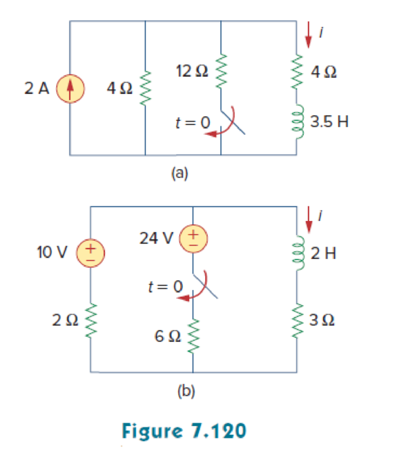
(a)
Calculate the value of inductor current
Answer to Problem 54P
The value of inductor current
Explanation of Solution
Given data:
Refer to Figure 7.120 in the textbook.
The value of inductance L in Figure 7.120(a) is
Formula used:
Write the general expression to find the complete response of current for the RL circuit.
Here,
Write the expression to calculate the time constant for the RL circuit.
Here,
L is the inductance of the inductor.
Calculation:
Figure 1 shows the modified circuit diagram when
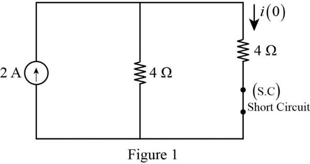
In Figure 1, the switch is kept in open position for all
Therefore, the inductor current
Figure 2 shows the modified circuit diagram when the switch is kept in close position for all
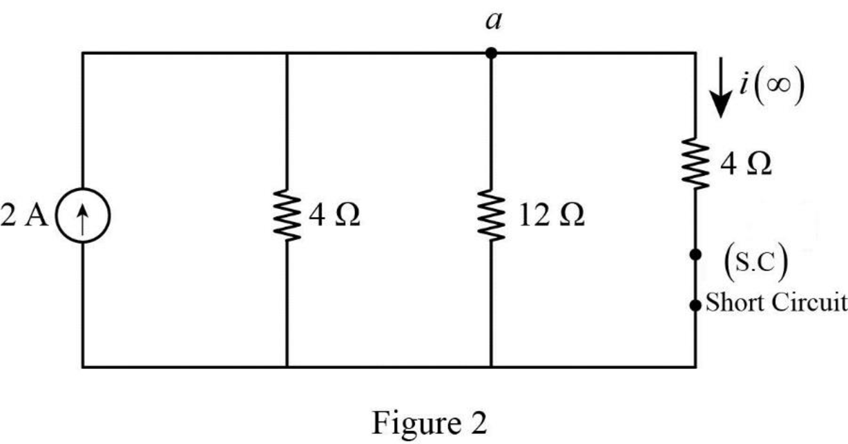
Apply Kirchhoff’s current law at node a.
Rearrange the equation as follows,
The final inductor current
Substitute
Figure 3 shows the equivalent resistance at the inductor terminal.
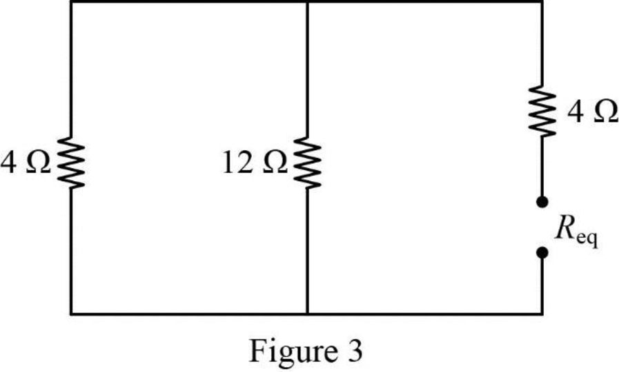
In Figure 3, the equivalent resistance is calculated as follows.
Substitute
Substitute the units
Substitute
Therefore, the inductor current
Conclusion:
Thus, the value of inductor current
(b)
Calculate the value of inductor current
Answer to Problem 54P
The value of inductor current
Explanation of Solution
Given data:
Refer to Figure 7.120 in the textbook.
The value of inductance L in Figure 7.120(b) is
Calculation:
Figure 4 shows the modified circuit diagram when switch is kept open for a long time at
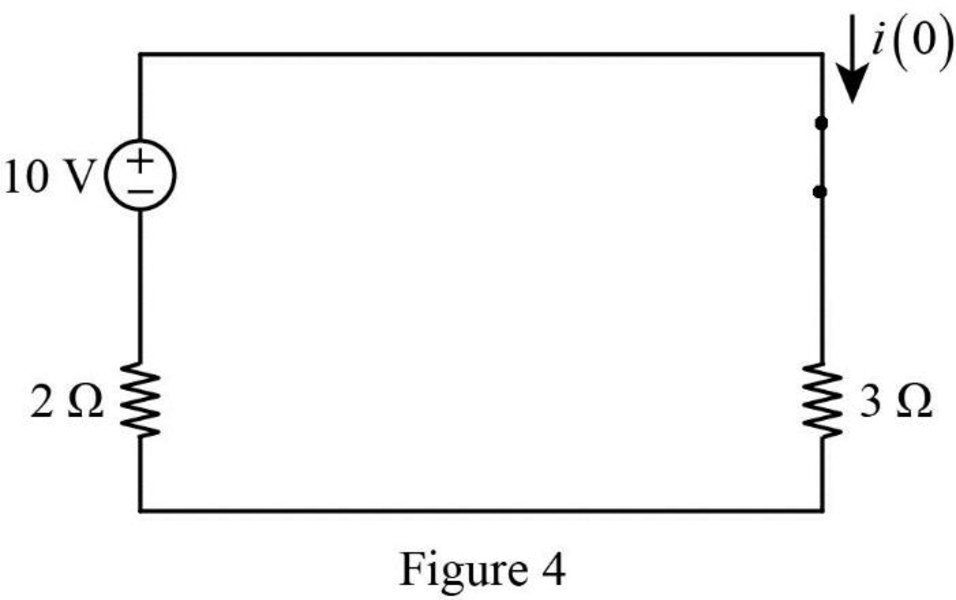
In Figure 4,
Rearrange the equation as follows,
Therefore, the inductor current
Figure 5 shows the redrawn circuit when switch is kept in closed position at
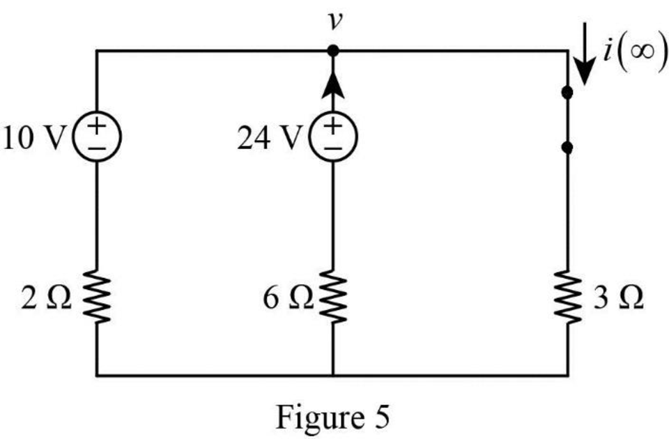
In Figure 5, apply Kirchhoff’s current law at node v.
Rearrange the equation as follows,
The final inductor current
Substitute
Figure 6 shows the equivalent resistance at the inductor terminal.
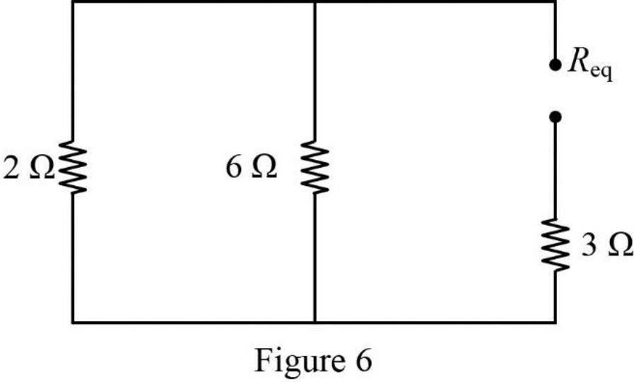
In Figure 6, the equivalent resistance is calculated as follows.
Substitute
Substitute the units
Substitute
Therefore, the inductor current
Conclusion:
Thus, the value of inductor current
Want to see more full solutions like this?
Chapter 7 Solutions
Fundamentals of Electric Circuits


- The initial voltage across the capacitor at t = 0 in the circuit shown is 2V. Voltage Vs is applied at t = 0; that is, Vs = 10 u(t) V. Find voltage v(t), t >= 0, across the capacitor.arrow_forwardIn the circuit below, the switch is closed at t=0 s. It is known that the voltage across the capacitor at t=0.2 s is Vc( t = 0.2 ) = 10.31 V. In this case, what will be the voltage Vc( t = 0.1 ) of the capacitor at t=0.1 s? Calculate.arrow_forwardIn the circuit below, the switch is closed at t=0 s. It is known that the voltage across the capacitor at t=0.2 s is Vc( t = 0.2 ) = 10.31 V. What is the initial energy of the capacitor in this case? Calculate.arrow_forward
- No energy is stored in the 100 mH inductor or the 0.4μF capacitor when theswitch in the circuit shown is closed. Find vC(t) for t≥0arrow_forwardFor the following circuit obtain: (a) the response v(t) for t>0, (b) the current i(t) through the inductor for t>0.arrow_forwardA series LR circuit has a variable inductor with theinductance L(t) is defined by intervals.Find the current i(t) if the resistance is 0.2 ohms, the voltageapplied is E(t) = 4 volts; knowing that i(0) = 0.arrow_forward
- Consider the following circuit in which the inductor current and the capacitor voltage are equal to zero at t = 0 s. Find the value of v at t = 2 s.arrow_forwardFind the energy stored in a 3 μF capacitor and v= 12 v.arrow_forwardFind Leq between the terminals a,b for the circuits shown below. Assuming the initial energy stored in the inductors is zero.arrow_forward
- In the circuit shown, the switch closes and is left closed for a long time. Then the switch is opened. Imediately after it is opened, what is the potential difference across the inductor L?arrow_forwardA capacitor with a capacitance of 29 microfarads is discharged through a resistance of 36 kilo-ohms. How many milliseconds does it take for the voltage to drop to 1/e of its initial value. Here "e" is the base of natural logarithms, about 2.718 .arrow_forwardDetermine the Norton equivalent circuit for the circuit below. The strong one, the inductor and the capacitor have the following values:arrow_forward
 Introductory Circuit Analysis (13th Edition)Electrical EngineeringISBN:9780133923605Author:Robert L. BoylestadPublisher:PEARSON
 Delmar's Standard Textbook Of ElectricityElectrical EngineeringISBN:9781337900348Author:Stephen L. HermanPublisher:Cengage Learning
 Programmable Logic ControllersElectrical EngineeringISBN:9780073373843Author:Frank D. PetruzellaPublisher:McGraw-Hill Education
 Fundamentals of Electric CircuitsElectrical EngineeringISBN:9780078028229Author:Charles K Alexander, Matthew SadikuPublisher:McGraw-Hill Education
 Electric Circuits. (11th Edition)Electrical EngineeringISBN:9780134746968Author:James W. Nilsson, Susan RiedelPublisher:PEARSON
 Engineering ElectromagneticsElectrical EngineeringISBN:9780078028151Author:Hayt, William H. (william Hart), Jr, BUCK, John A.Publisher:Mcgraw-hill Education,