
Concept explainers
Videos
(a)
Calculate the energy stored in each energy storage element.
(a)
Answer to Problem 70E
The value of energy stored in the inductor
Explanation of Solution
Given data:
Refer to Figure 7.84 in the textbook.
Calculation:
The given circuit is redrawn as shown in Figure 1.
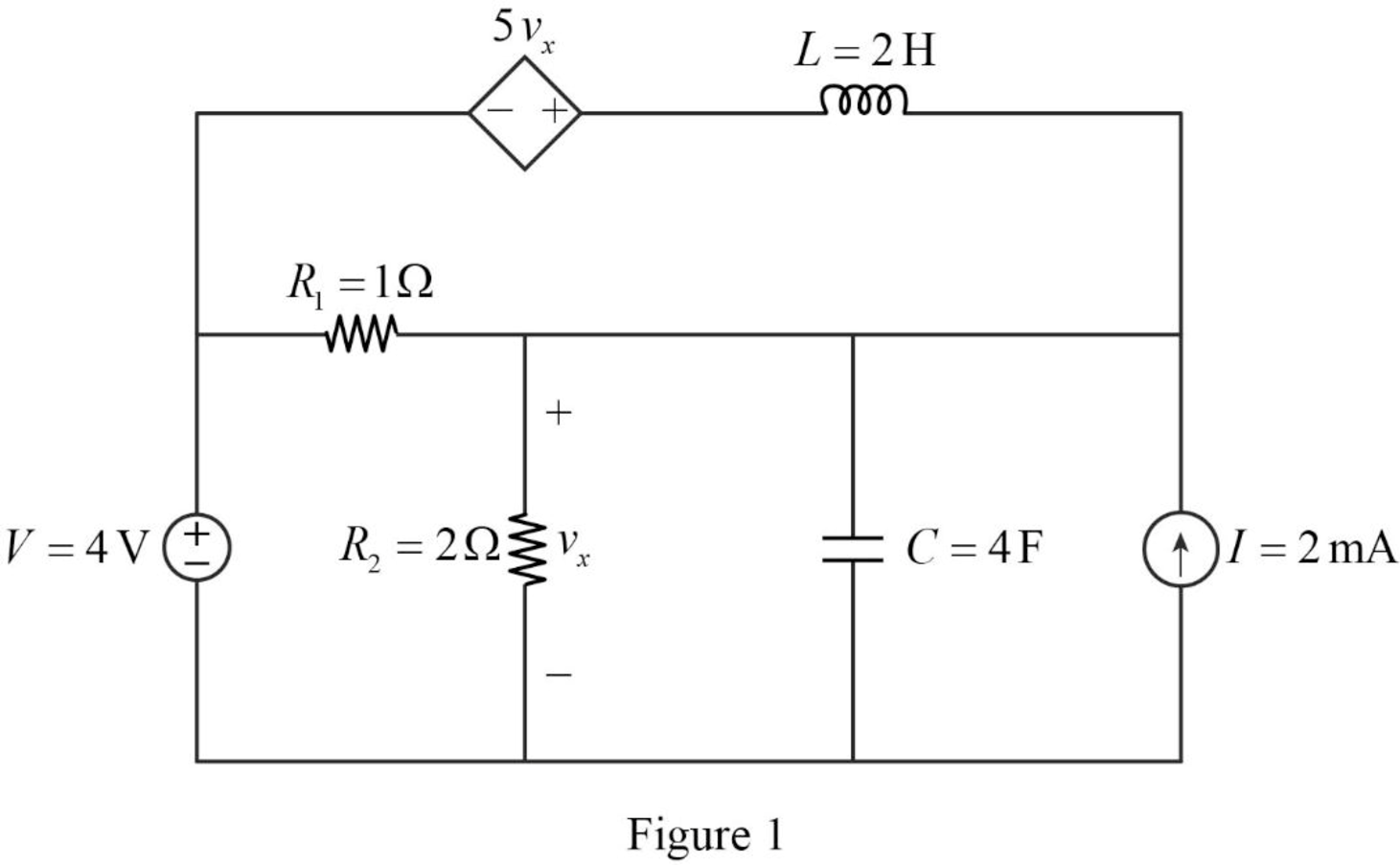
For a DC circuit, at steady state condition, the capacitor acts like open circuit and the inductor acts like short circuit.
Now, the Figure 1 is reduced as shown in Figure 2.
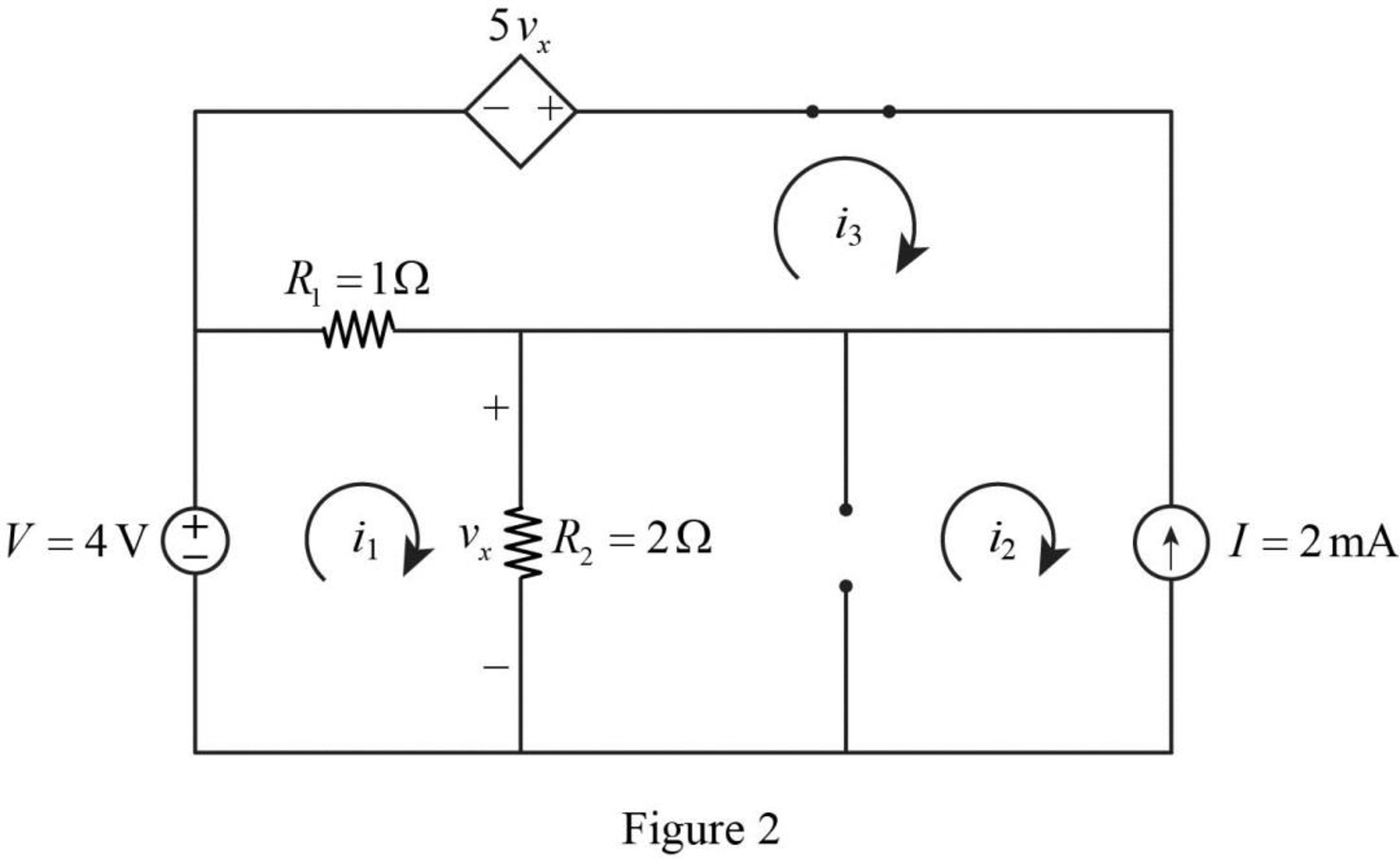
Apply Kirchhoff’s voltage law for loop 1 in Figure 2.
Refer to Figure 2, the current
Substitute
Simplify the above equation to find
Apply Kirchhoff’s voltage law for loop 3 in Figure 2.
Refer to Figure 2, the voltage across the resistor
The voltage
Substitute equation (4) in (3).
Substitute
Substitute equation (2) in (5).
Simplify the above equation to find
Substitute
Refer to Figure 2, the current
Substitute
Refer to Figure 2, the resistor
Write a general expression to calculate the energy stored in a inductor.
Here,
Write a general expression to calculate the energy stored in a capacitor.
Here,
Substitute
Simplify the above equation to find
Substitute
Simplify the above equation to find
Conclusion:
Thus, the value of energy stored in the inductor
(b)
Verify the calculated answers with an appropriate simulation.
(b)
Explanation of Solution
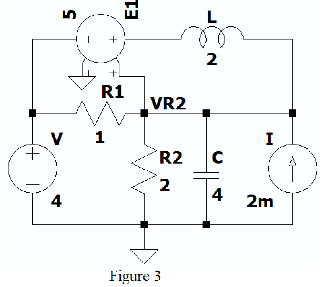
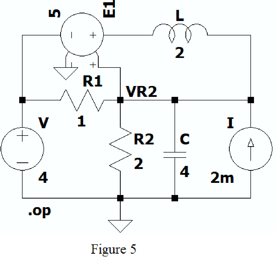
Create the new schematic in LTspice and draw the Figure 1 as shown in Figure 3. Use the Label net option and write VR2 to find voltage across resistor
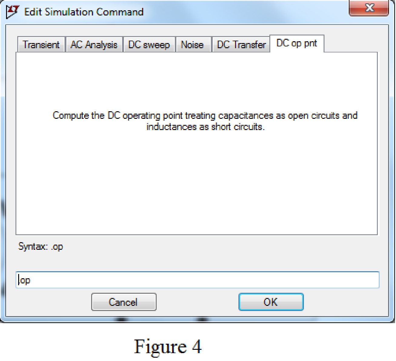
Choose the Dc op point in Edit simulation Cmd as shown in Figure 4.
After adding the above mentioned commands the circuit becomes as shown in Figure 5.
Now run the simulation, the table will be displayed with the values of current through resistors, capacitor and voltage across the capacitor as shown in Figure 6.
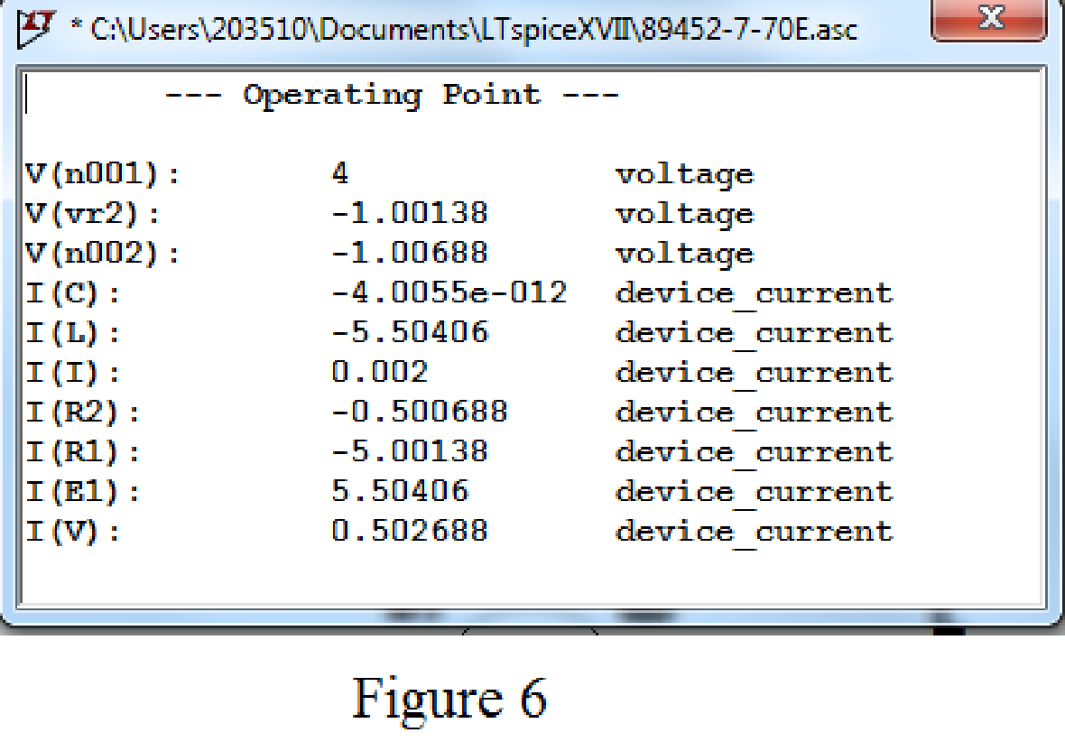
Refer to Figure 6, the value of voltage across the capacitor
Conclusion:
Thus, the calculated answers are verified with an appropriate SPICE simulation.
Want to see more full solutions like this?
Chapter 7 Solutions
Loose Leaf for Engineering Circuit Analysis Format: Loose-leaf


- 7. 7.27 In the circuit the voltage and current expressions are v=48e−25t V, t≥0;i=12e−25t mA, t≥0+.Find1. a) R.2. b) C.3. c) τ (in milliseconds).4. d) the initial energy stored in the capacitor.5. e) the amount of energy that has been dissipated by the resistor 60ms after the voltage begins to decay.arrow_forwardhow do i solve the attached electronics question, specifically number 7, 6 given for contextarrow_forward7.4 The switch in the circuit shown has been closed for a long timebefore being opened at t=0.2. b) What percentage of the initial energy stored in the circuit hasbeen dissipated after the switch has been open for 60 ms?arrow_forward
- For the circuit shown, calculate 1. the initial energy stored in the capacitors; 2. the final energy stored in the capacitors; 3. the total energy delivered to the black box; 4. the percentage of the initial energy stored that is delivered to the black box; and 5. the time, in milliseconds, it takes to deliver 7.5 mJ to the black box.arrow_forwardAn iron ring 20 cm mean radius is made of square of iron of 3 cm × 3 cm cross-section and is uniformly wound with 350 turns of wire of 2 mm2 cross-section. Calculate the value of the self-inductance of the coil. Assume μr = 800.arrow_forwardImplementation process for the design of a PIEZOELECTRIC TILE PROTOTYPE FOR THE GENERATION OF ELECTRIC ENERGY THROUGH THE PEDESTRIAN TRAFFIC.note: please do not use artificial intelligence AIarrow_forward
- 1. Theoretically calculate the voltage across the capacitor in the circuit of Figure 1 when t = 0 s, 5 s, 10 s, 20 s, 30 s, 40 s, and 60 s, assuming that the circuit is under DC conditions when t < 0 s and the switch is opened at t = 0 s. 2. Compare the calculated voltage at t = 20 s with the experimentally measured ∆?.arrow_forwardsolve for the computed values only, please show complete solution.arrow_forwardCalculate the energy stored in a parallel-plate capacitor which consists of two metal plates, each 60cm2 separated by a dielectric 1.5mm thick and of relative permittivity 3.5 if a p.d. of 1000 v is applied across it.arrow_forward
- 1. Find the outer radius of a coaxial cable having a characteristic impedance of 12 and a dielectric constant of 0.06. The outer inner radius of this cable is 4 cm. 2. How much is the inductance of a coil of an instrument that induces 1000 V when its current changes at the rate of 50 mA in 2 µsarrow_forwardThe switch in the circuit shown in Fig. 7.21 has been in position a for a longtime. At t=0, the switch moves from position a to position b. The switch is amake-before-break type; that is, the connection at position b is establishedbefore the connection at position a is broken, so the inductor current iscontinuous.5. Plot both i(t) and v(t) versus t.arrow_forwardIn particular, a system may or may not be(1) Memoryless(2) Time invariant(3) Linear(4) Causal(S) StableDetermine which of these properties hold and which do not hold for the following continuous-time system. Justify your answers.arrow_forward
 Introductory Circuit Analysis (13th Edition)Electrical EngineeringISBN:9780133923605Author:Robert L. BoylestadPublisher:PEARSON
 Delmar's Standard Textbook Of ElectricityElectrical EngineeringISBN:9781337900348Author:Stephen L. HermanPublisher:Cengage Learning
 Programmable Logic ControllersElectrical EngineeringISBN:9780073373843Author:Frank D. PetruzellaPublisher:McGraw-Hill Education
 Fundamentals of Electric CircuitsElectrical EngineeringISBN:9780078028229Author:Charles K Alexander, Matthew SadikuPublisher:McGraw-Hill Education
 Electric Circuits. (11th Edition)Electrical EngineeringISBN:9780134746968Author:James W. Nilsson, Susan RiedelPublisher:PEARSON
 Engineering ElectromagneticsElectrical EngineeringISBN:9780078028151Author:Hayt, William H. (william Hart), Jr, BUCK, John A.Publisher:Mcgraw-hill Education,