
Concept explainers
Videos
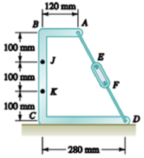
Knowing that the turnbuckle has been tightened until the tension in wire AD is 850 N, determine the internal forces at the point indicated: 7.154 Point J.
The internal forces.
Answer to Problem 7.154RP
The internal forces are
Explanation of Solution
The free body diagram is given in figure 1.
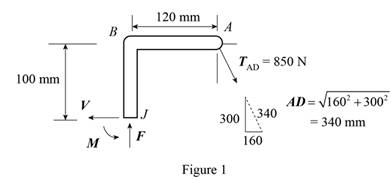
From the diagram, net force along horizontal and vertical directions is zero. Write the equilibrium condition for the forces.
Here,
The net moment at point J is zero. Therefore, the equilibrium condition is,
Here, M is the moment of internal force.
Conclusion:
Substitute 280 mm for CD, 120 mm for AB, 300 mm for BC and 850 N for
Substitute 280 mm for CD, 120 mm for AB, 300 mm for BC and 850 N for
Substitute 400 N for V, 750 N for F, 100 mm for BJ and 120 mm for AB in the expression for M.
Therefore, the internal forces are
Want to see more full solutions like this?
Chapter 7 Solutions
Vector Mechanics for Engineers: Statics


- Knowing that the tension in cable AC is 2130 N, determine the components of the force exerted on the plate at C.arrow_forwardA semicircular rod is loaded as shown. Determine the internal forces at point J knowing that 0== 30°.arrow_forwardKnowing that the radius of each pulley is 150 mm, that a = 20°, and neglecting friction, determine the internal forces at (a) point J, (b) point K.arrow_forward
- Two cables are tied together at C and are loaded as shown. Knowing that P = 830, α = 39.2° and θ = 52.5°, determine the tension in cable AC.arrow_forwardA machine component is subjected to the forces and couples shown. The component is to be held in place by a single rivet that can resist a force but not a couple. For P = 0, determine the location of the rivet hole if it is to be located (a) on line FG , (b) on line GH.arrow_forwardA machine component is subjected to the forces and couples shown.The component is to be held in place by a single rivet that can resista force but not a couple. For P=0, determine the location of the rivet hole if it is to be located (a) on line FG, (b) on line GH.arrow_forward
- For the frame and loading shown, determine the internal forces at the point indicated:Point Jarrow_forwardA 10-ft rope is attached to two supports A and b as shown. Determine (a) the span of the rope for which the span is equal to the sag, (b) the corresponding angle 0B.arrow_forwardA frame ABC is supported in part by cable DBE that passes through a frictionless ring at B. Knowing that the tension in the cable is 385 N, determine the magnitude and direction of the resultant of the forces exerted by the cable at B.arrow_forward
- The end of the coaxial cable AE is attached to the pole AB, which is strengthened by the guy wires AC and AD. Knowing that the tension in wire AD is 85 lb, determine (a) the components of the force exerted by this wire on the pole, (b) the angles θx, θy, and θz that the force forms with the coordinate axes.arrow_forwardA steam pipe weighing 45 lb/ft that passes between two buildings 40 ft apart is supported by a system of cables as shown. Assuming that the weight of the cable system is equivalent to a uniformly distributed loading of 5 lb/ft, determine (a) the location of the lowest point C of the cable, (b) the maximum tension in the cable.arrow_forwardThe AB bar is supported by the AC string. Knowing that c = 436 mm) and that the moment of the rope in relation to B of the force exerted by the rope at point A is 754 N.m, determine the traction on the rope.arrow_forward
 International Edition---engineering Mechanics: St...Mechanical EngineeringISBN:9781305501607Author:Andrew Pytel And Jaan KiusalaasPublisher:CENGAGE L