
Concept explainers
(a)
Find the quantity of water flowing through the sample per hour.
(a)
Answer to Problem 7.1CTP
The quantity of water flowing through the sample per hour is
Explanation of Solution
Given information:
The length of each soil layer
The total length of the soil layer H is 600 mm.
The diameter of the cylindrical tube d is 150 mm.
The constant head difference
The porosity of the soil layer I
The porosity of the soil layer II
The porosity of the soil layer III
The hydraulic conductivity of soil layer I
The hydraulic conductivity of soil layer II
The hydraulic conductivity of soil layer III
Calculation:
Determine the hydraulic conductivity in the vertical direction using the relation.
Substitute 600 mm for H, 200 mm for
Determine the hydraulic gradient using the relation.
Here, L is the total length of the soil layer.
Substitute 470 mm for
Determine the area of the cylindrical tube using the relation.
Substitute 150 mm for d.
Determine the rate of seepage per unit length of the dam using the relation.
Substitute
Therefore, the quantity of water flowing through the sample per hour is
(b)
Find the elevation head (Z), pressure head
(b)
Answer to Problem 7.1CTP
The elevation head (
The pressure head
The total head
The elevation head (
The pressure head
The total head
The elevation head (
The pressure head
The total head
The elevation head (
The pressure head
The total head
Explanation of Solution
Given information:
The length of each soil layer
The total length of the soil layer H is 600 mm.
The diameter of the cylindrical tube d is 150 mm.
The constant head difference
The porosity of the soil layer I
The porosity of the soil layer II
The porosity of the soil layer III
The hydraulic conductivity of soil layer I
The hydraulic conductivity of soil layer II
The hydraulic conductivity of soil layer III
Calculation:
Determine the elevation head (
Here,
Substitute 220 mm for
Therefore, the elevation head (
Determine the pressure head
Substitute 470 mm for
Therefore, the pressure head
Determine the total head
Substitute 690 mm for
Therefore, the total head
Determine the elevation head (
Substitute 220 mm for
Therefore, the elevation head (
Determine the value of
Substitute
Determine the total head
Substitute 470 mm for
Therefore, the total head
Determine the pressure head
Substitute 436.3 mm for
Therefore, the pressure head
Determine the elevation head
Substitute 220 mm for
Therefore, the elevation head (
Determine the value of
Substitute
Determine the total head
Substitute 436.3 mm for
The total head
Determine the pressure head
Substitute 432.3 mm for
Therefore, The pressure head
Determine the elevation head
Substitute 220 mm for
Therefore, the elevation head (
Determine the value of
Substitute
Determine the total head
Substitute 432.3 mm for
Therefore, the total head
Determine the pressure head
Substitute 432.3 mm for
Therefore, the pressure head
(c)
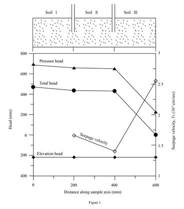
Plot the variation of the elevation head, pressure head, and the total head with the horizontal distance along the sample axis (X–X).
(c)
Explanation of Solution
Given information:
The length of each soil layer
The total length of the soil layer H is 600 mm.
The diameter of the cylindrical tube d is 150 mm.
The constant head difference
The porosity of the soil layer I
The porosity of the soil layer II
The porosity of the soil layer III
The hydraulic conductivity of soil layer I
The hydraulic conductivity of soil layer II
The hydraulic conductivity of soil layer III
Calculation:
Refer Part b)
Draw the graph between the elevation head pressure head, and the total head with the horizontal distance along the sample axis (X–X) as in Figure (1).
(d)
Plot the variation of the discharge velocity and the seepage velocity along the sample axis (X–X).
(d)
Explanation of Solution
Given information:
The length of each soil layer
The total length of the soil layer H is 600 mm.
The diameter of the cylindrical tube d is 150 mm.
The constant head difference
The porosity of the soil layer I
The porosity of the soil layer II
The porosity of the soil layer III
The hydraulic conductivity of soil layer I
The hydraulic conductivity of soil layer II
The hydraulic conductivity of soil layer III
Calculation:
Determine the discharge velocity v using the relation.
Substitute
Determine the seepage velocity of soil I using the relation.
Here,
Substitute 0.000843 cm/sec for v and 0.5 for
Determine the seepage velocity of soil II using the relation.
Here,
Substitute 0.000843 cm/sec for v and 0.6 for
Determine the seepage velocity of soil III using the relation.
Here,
Substitute 0.000843 cm/sec for v and 0.33 for
Draw graph of variation of the discharge velocity and the seepage velocity along the sample axis (X–X).
Refer Figure (1) in Part (c).
(e)
Find the height of the vertical columns of water inside piezometers A and B installed on the sample axis.
(e)
Answer to Problem 7.1CTP
The height of the vertical columns of water at point A is
The height of the vertical columns of water at point B is
Explanation of Solution
Given information:
The length of each soil layer
The total length of the soil layer H is 600 mm.
The diameter of the cylindrical tube d is 150 mm.
The constant head difference
The porosity of the soil layer I
The porosity of the soil layer II
The porosity of the soil layer III
The hydraulic conductivity of soil layer I
The hydraulic conductivity of soil layer II
The hydraulic conductivity of soil layer III
Calculation:
The height of water column is equal to the Piezometric or pressure head at a point.
Determine the height of water in point A.
Substitute 656.3 mm for
Therefore, the height of the vertical columns of water at point A is
Determine the height of water in point B.
Substitute 652.3 mm for
Therefore, the height of the vertical columns of water at point B is
Want to see more full solutions like this?
Chapter 7 Solutions
Principles of Geotechnical Engineering (MindTap Course List)


- The figure shows the layers of soil in the tube that is 10 cm by 10 cm in cross section. When the tube is supplied with water, a constant head difference of 30 cm is observed. The coefficient of permeability of each sample are as follows: A. Find the equivalent coefficient of permeability. B. Determine the hydraulic gradient. C. Compute the rate of water supply.arrow_forwardA soil profile consisting of three layers is shown in the below figure. Calculate the values of o, u, and o' at points A, B, C, and D for the following case:arrow_forwardThe figure shows a layer of soil in a tube that is 100mm x 100mm in cross section. Water is supplied to maintain a constant head difference of 400mm across the sample. The height of each soil sample is 100mm. and the total length from point A to B is 288cm. Calculate the equivalent k in terms of 10^-6 cm/sec from point A to B if k1. k2, and k3 is equal to 1x10^-2 cm/sec, 32x10^-3 cm/sec, and 4.9x10^-4 cm/sec, respectively. Consider that the length of the first soil sample in the left is 40% of the total length, and the soil sample in the middle and right side were both having 30% of the total length. asap solution plsarrow_forward
- The given values are as follows: The specimen's e=0.46 length of soil specimen=450mm constant head difference=700mm Water collected in 3 minutes =3.54x10⁻⁴ m3 Area=2.26x10⁻³ m2 1) Find the coefficient of permeability (Ans. 2.012 m/hr) 2) Find the discharge velocity (Ans. 0.052 m/min) 3) Find the interstitial velocity (Ans. 0.165 m/min)arrow_forwardFrom the figure shown 1. What is the equation in determining the equivalent coefficient of permeability in the horizontal direction. 2. What is the equivalent coefficient of permeability in the horizontal direction if each soil layer is 3 m. thick and has the given values of K1, K2, K3 and K4. 3. What is the total flow if iav = 0.70arrow_forwardQuestion-2: A soil profile is shown in Figure 2.1. Calculate and plot the variation of total vertical stress, pore pressure and effective vertical stress with depth.arrow_forward
- The figure shows water flowing through two saturated soils (A and B) in the hatched areas. Calculate the pressure head elevation head and total head at points X, Y and Z. Also calculate the flow rate through the soils. the cross sectional area of the sample is 15 m2arrow_forwardThe figure below shows the layers of soil in a tube 100 mm x 100 mm in cross section. Water is supplied to maintain a constant head difference of H across the sample. Hydraulic conductivities of each soil are tabulated below. All measurements in the figure are millimeters. If H = 1.98 and the Hydraulic conductivity of soil E is 0.002 m/s. a. Determine the equivalent hydraulic conductivity of the system in the direction of the flow. b. Find the h1 and h2. c. Determine the rate of flow.arrow_forwardPressure (kN/m²)27 54 107 214 429 214 107 54 Void ratio1.243 1.217 1.144 1.068 0.994 1.001 1.012 1.024 The table above shows results obtained from an oedometer test on a specimen of saturated clay. A layer of this clay 2.5 m thick lies below a 10 m depth of sand, the water table being at the surface. The saturated weight for both soils is 19 kN/m³. A 10-m depth of fill of unit weight of 21 kN/m³ is placed on the sand over an extensive area. If the fill was to be removed some time after the completion of consolidation, what heave (mm) would eventually take place due to swelling of the clay? (0 d.p). Use unit weight of water of 9.8 kN/m3. Use log base 10.arrow_forward
- For a falling or variable head permeability test, the following are given: Length of soil specimen = 12 cm. Cross sectional area of stand pipe: A = 0.018 cm2 Diameter of soil specimen = 7.5 cm. Time of collection of water: t = 65 sec. Head difference at time t = 0; h1 = 70 cm. Head difference at time t = 65 sec; h2 = 40 cm. Temperature of water: 14 ֯C Find the absolute permeability of the soil at 20 ֯C.arrow_forwardA soil profile consisting of three layers is shown in the figure. Calculate the values of the total stress, effective stress ad pore waterpressureat points A, B, C, and D for the following cases. In each case, plot the variations with depth. Characteristics of layers 1, 2, and 3 for each case are given belowarrow_forwardConsider the upward flow of water through a layer of sand in a tank as shown in Figure QI(c), For the sand, the following are given: void ratio (e) = 0.52 and specific gravity of solid = 2.67. Determine: (i) Total stress, pore water pressure and effective stress at points A and B (ii) The upward seepage force per unit volume of soil.arrow_forward
 Principles of Geotechnical Engineering (MindTap C...Civil EngineeringISBN:9781305970939Author:Braja M. Das, Khaled SobhanPublisher:Cengage Learning
 Fundamentals of Geotechnical Engineering (MindTap...Civil EngineeringISBN:9781305635180Author:Braja M. Das, Nagaratnam SivakuganPublisher:Cengage Learning