
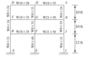
The effective length factors for columns IJ, FG and GH of the given frame.
Answer to Problem 7.1PFS
The effective length factor for column IJ, FG and GH is 1.23, 1.11 and 1.10.
Explanation of Solution
Given:
The given frame is,
Formula used:
The rotational stiffness is given by,
Here,
Calculation:
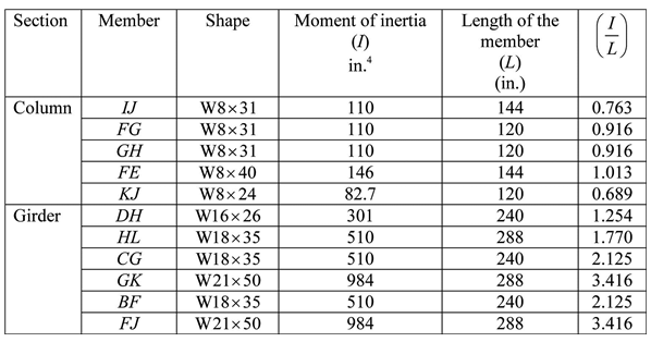
From table 1-1, W-shapes properties in the AISC steel construction manual,
The moment of inertia for the section W8x31 is 110 in4.
The moment of inertia for the section W8x24 is 82.7 in4.
The moment of inertia for the section W18x35 is 510 in4.
The moment of inertia for the section W21x50 is 984 in4.
The moment of inertia for the section W16x26 is 301 in4.
The moment of inertia for the section W8x40 is 146 in4.
Calculate the ratio of moment of inertia to the length of member for frame.
For member IJ,
Similarly calculate the ratio of moment of inertia to the length of member for frame and shown in table below.
Consider the column IJ .
Since column IJ is a pinned column so the rotational stiffness for A is 10.
Calculate the rotational stiffness for B .
Refer the figure 7.2, "Side sway uninhibited” (Moment frame) of the textbook to find the effective length factor for
The effective length factor for column IJ is 1.23.
Consider the column FG .
Calculate the rotational stiffness for A .
Calculate the rotational stiffness for B .
Refer the figure 7.2, "Side sway uninhibited” (Moment frame) of the textbook to find the effective length factor for
The effective length factor for column FG is 1.11.
Consider the column GH .
Calculate the rotational stiffness for A .
Calculate the rotational stiffness for B .
Refer the figure 7.2, "Side sway uninhibited” (Moment frame) of the textbook to find the effective length factor for
Conclusion:
Hence, the effective length factor for column IJ, FG and GH is 1.23, 1.11 and 1.10.
Want to see more full solutions like this?
Chapter 7 Solutions
Structural Steel Design (6th Edition)

- A base plate is to be designed for a W12 x 152 column (Fy = 50 ksi) that supports the loads PD = 200 k and PL = 450 k. Select an A36 plate (Fy = 36 ksi) to cover the entire area of the 3 ksi concrete pedestal underneath.arrow_forwardDetermine the design moment strength and the position of the neutral axis of a rectangular section that has b = 300 mm, d = 500 mm, and is reinforced with five 20-mm-diameter bars. Given f ′c = 20 MPa and fy = 400MPa.arrow_forwardSelect a cover-plated W section limited to a maximum depth of 21.00 in to support the service loads shown in the accompanying figure. Use A36 steel and assume the beam has full lateral bracing for its compression flange.arrow_forward
- Determine the available strength of the compression member made of a single angle L 5x3x1/2 with a length of 15 feet. Compute design strengths for both LRFD and ASDarrow_forwardThe figure shown is to be reinforced with 12mm U-stirrups for the rectangular section using fc=22MPa and fy=418MPa. Use the simplified calculation for Vc. Use the provisions of NSCP 2015 . Determine the spacing of stirrups required by torsion, mm. Determine the spacing of stirrups required by shear, mm. Determine the spacing required by shear and torsion following the specifications of NSCP 2015, mm.arrow_forwardA one-way interior slab panel, continuous on both ends, is built integrally with the beam supports. It has an unsupported span if 3.2m. and carries a total factored uniformly distributed load (including self-weight) of 11.2 KPa. Use D12mm reinforcement, fc’ = 28MPa and fy=350MPa. Design the slab and draw the details.arrow_forward
- A built-up beam is composed of 4-75x75x4 mm angles connected to a 6 mm x 400 mm web plate and 300x6 mm cover plates as shown in Fig P307. Verify if the section compactness using Fy = 348 MPa. The bolts are located at the center of the angle legs.arrow_forwardQ1- the reinforced flat plate roof slab system that shownin figure. Supports a service live load of 1.5 kN / m2 and a service superimposed dead load of 3.4 kN / m? in addition to its own weight. The slab is supported along its outer edges by a brick wall. Slab thickness is 200mm and wall thickness is 240mm. all interior columns are 300x600 mm. Using the ACI direct design method, design and detail the column strip top bars required at the continuous edges of strip A shown in the plan. Use fe-22 MPa andf-400MP.arrow_forwardDetermine the compressive load carrying capacity (both LRFD and ASD) for a W14x211 section. The column has overall length of 30 ft, fixed at one end and hinged at other end.arrow_forward
- a simply-supported rectangular concrete beam with a width of 300mm wide, 600 mm total depth, and a 5.8m long, is needed to accommodate both ceiling height clearance below and the superimposed loads. if f'c = 28mpa and steel fy = 415 mpa Compute the allowable resisting moment of the section shown using transformed area if allowable stresses are fc = 0.45, fs = fs- = 0.60, and n = 8. whats the allowable resisting moment of beam using strength design method?arrow_forwardA W14x43 grade 50 steel column is supporting a service dead load of 600 kips and a service live load of 1800 kips. The column is supported on a reinforced concrete footing of 3000 psi concrete strength. Design the base plate for the column as per AISC/LRFD design method. Use A36 steel.arrow_forwardA rectangular beam has b=300mm and d=520mm. Determine As(max) if fc'=27.5MPa and fy=415MPa. Use 2015 NSCParrow_forward

 Structural Analysis (10th Edition)Civil EngineeringISBN:9780134610672Author:Russell C. HibbelerPublisher:PEARSON
 Principles of Foundation Engineering (MindTap Cou...Civil EngineeringISBN:9781337705028Author:Braja M. Das, Nagaratnam SivakuganPublisher:Cengage Learning
 Fundamentals of Structural AnalysisCivil EngineeringISBN:9780073398006Author:Kenneth M. Leet Emeritus, Chia-Ming Uang, Joel LanningPublisher:McGraw-Hill Education
 Traffic and Highway EngineeringCivil EngineeringISBN:9781305156241Author:Garber, Nicholas J.Publisher:Cengage Learning