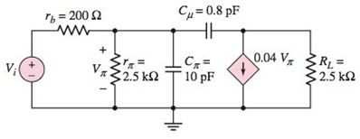
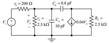
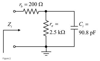
Problem 7.1EP: (a) For the circuit shown in Figure 7.2, the parameters are RS=2k and RP=8k . (i) If the corner... Problem 7.2EP: The circuit shown in Figure 7.10 has parameters of RP=7.5k and CP=80pF . The midband gain is 2 dB... Problem 7.1TYU: For the equivalent circuit shown in Figure 7.13, the parameters are: RS=1k , r=2k , RL=4k ,... Problem 7.2TYU: The equivalent circuit in Figure 7.14 has circuit parameters RS=100 , r=2.4k , gm=50mA/V , RL=10k ,... Problem 7.3TYU: The parameters in the circuit shown in Figure 7.15 are RS=100 , r=2.4k , gm=50mA/V , RL=10k , CC=5F... Problem 7.3EP: For the circuit shown in Figure 7.2 1(a), the parameters are: VCC=3V , RSi=0 , R1=110k , R2=42k ,... Problem 7.4EP: Consider the circuit shown in Figure 7.22(a). The bias voltages arechanged to V+=3V and V=3V . Other... Problem 7.5EP: For the emitterfollower circuit shown in Figure 7.23(a), determine therequired value of CC2 to yield... Problem 7.7EP: The circuit shown in Figure 7.27(a) has parameters V+=10V , V=10V , RS=0.5k , RE=4k ,and RC=2k... Problem 7.4TYU: Consider the common-base circuit shown in Figure 7.33. Can the two coupling capacitors be treated... Problem 7.5TYU: The commonemitter circuit shown in Figure 7.34 contains both a coupling capacitor and an emitter... Problem 7.8EP: A bipolar transistor has parameters o=120 , C=0.02pF , and f=90MHz and is biased at ICQ=0.2mA . (a)... Problem 7.9EP Problem 7.10EP: For the circuit in Figure 7.41(a), the parameters are, R1=200k , R2=220k RC=2.2k , RC=2.2k , RL=4.7k... Problem 7.6TYU: A bipolar transistor is biased at ICQ=120A and its parameters are o=120 , C=0.08pF , and f=15MHz .... Problem 7.7TYU: For the transistor described in Example 7.9 and biased at the same Qpoint,determine |hfe| and the... Problem 7.8TYU: The parameters of a bipolar transistor are: o=150 , fT=1GHz , r=12k , and C=0.15pF . (a) Determine C... Problem 7.11EP: The parameters of an nchannel MOSFET are Kn=1.2mA/V2 , VTN=0.5V , =0. , Cgd=8fF , and Cgs=60fF . The... Problem 7.12EP: For the circuit in Figure 7.55, the transistor parameters are Kn=0.8mA/V2 , VTN=2V , =0 , Cgs=100fF... Problem 7.9TYU: An nchannel MOSFET has parameters Kn=0.4mA/V2 , VTN=1V , and =0 . (a) Determine the maximum source... Problem 7.10TYU: An nchannel MOSFET has a unitygain bandwidth of fT=1.2GHz . Assume overlap capacitances of... Problem 7.11TYU: For a MOSFET, assume that gm=1.2mA/V . The basic gate capacitancesare Cgs=60fF , Cgd=0 , and the... Problem 7.13EP: The transistor in the circuit in Figure 7.60 has parameters =125 , VBE(on)=0.7V , VA=200V , C=24pF ,... Problem 7.14EP: Consider the commonbase circuit in Figure 7.64. The transistor parameters are =100 , VBE(on)=0.7V ,... Problem 7.15EP: The cascode circuit in Figure 7.65 has parameters V+=12V , V=0 , R1=58.8k , R2=33.3k R3=7.92k ,... Problem 7.12TYU Problem 7.13TYU: For the circuit in Figure 7.72, the transistor parameters are: VTN=1V , Kn=1mA/V2 , =0 , Cgd=0.4pF ,... Problem 1RQ: Describe the general frequency response of an amplifier and define the lowfrequency, midband, and... Problem 2RQ: Describe the general characteristics of the equivalent circuits that apply to the lowfrequency,... Problem 3RQ: Describe what is meant by a system transfer function in the sdomain. Problem 4RQ: What is the criterion that defines a corner, or 3dB, frequency? Problem 5RQ: Describe what is meant by the phase of the transfer function. Problem 6RQ: Describe the time constant technique for determining the corner frequencies. Problem 7RQ: Describe the general frequency response of a coupling capacitor, a bypasscapacitor, and a load... Problem 8RQ: Sketch the expanded hybrid model of the BJT. Problem 9RQ Problem 10RQ Problem 11RQ Problem 12RQ: Sketch the expanded smallsignal equivalent circuit of a MOSFET. Problem 13RQ: Define the cutoff frequency for a MOSFET. Problem 14RQ Problem 15RQ: Why is there not a Miller effect in a commonbase circuit? Problem 16RQ: Describe the configuration of a cascode amplifier. Problem 17RQ: Why is the bandwidth of a cascode amplifier larger, in general, than that of asimple commonemitter... Problem 18RQ: Why is the bandwidth of the emitterfollower amplifier the largest of the three basic BJT amplifiers? Problem 7.1P Problem 7.2P Problem 7.3P: Consider the circuit in Figure P7.3. (a) Derive the expression for the voltagetransfer function... Problem 7.4P: Consider the circuit in Figure P7.4 with a signal current source. The circuitparameters are Ri=30k ,... Problem 7.5P: Consider the circuit shown in Figure P7.5. (a) What is the value of the voltage transfer function... Problem 7.7P: A voltage transfer function is given by T(f)=1/(1+jf/fT)3 . (a) Showthat the actual response at f=fT... Problem 7.8P: Sketch the Bode magnitude plots for the following functions: T1(s)=ss+100 T2(s)=5s/2000+1... Problem 7.10P: (a) Determine the transfer function corresponding to the Bode plot of themagnitude shown in Figure... Problem 7.11P: Consider the circuit shown in Figure 7.15 with parameters RS=0.5k , r=5.2k , gm=29mA/V , and RL=6k .... Problem 7.12P: For the circuit shown in Figure P7.12, the parameters are R1=10k , R2=10k , R3=40k , and C=10F . (a)... Problem 7.13P: The circuit shown in Figure 7.10 has parameters RS=1k , RP=10k ,and CS=CP=0.01F . Using PSpice, plot... Problem 7.14P: The transistor shown in Figure P7.14 has parameters VTN=0.4V , Kn=0.4mA/V2 ,and =0 . The transistor... Problem 7.15P: Consider the circuit shown in Figure P7.15. The transistor has parameters =120 and VA= . The circuit... Problem 7.16P: The transistor in the circuit shown in Figure P7.16 has parameters VTN=0.4V , Kn=50A/V2 , and... Problem 7.17P: For the common-emitter circuit in Figure P7.17, the transistor parametersare: =100 , VBE(on)=0.7V ,... Problem D7.20P: The transistor in the circuit in Figure P7.20 has parameters KP=0.5mA/V2 , VTP=2V , and =0 . (a)... Problem 7.21P: For the circuit in Figure P7.21, the transistor parameters are =120 , VBE(on)=0.7V , and VA=50V .... Problem 7.22P: (a) For the circuit shown in Figure P7.22, write the voltage transfer function T(s)=Vo(s)/Vi(s) .... Problem 7.23P: Consider the circuit shown in Figure P7.23. (a) Write the transfer function T(s)=Vo(s)/Vi(s) .... Problem 7.24P: The parameters of the transistor in the circuit in Figure P7.24 are VBE(on)=0.7V , =100 , and VA= .... Problem 7.25P: A capacitor is placed in parallel with RL in the circuit in Figure P7.24. Thecapacitance is CL=10pF... Problem 7.26P: The parameters of the transistor in the circuit in Figure P7.26 are KP=1mA/V2 , VTP=1.5V , =0 . (a)... Problem D7.27P Problem 7.28P: The circuit in Figure P7.28 is a simple output stage of an audio amplifier.The transistor parameters... Problem 7.29P: Reconsider the circuit in Figure P728. The transistor parameters are =120 , VBE(on)=0.7V , and VA= .... Problem 7.32P: Consider the circuit shown in Figure P7.32. The transistor parameters are =120 , VBE(on)=0.7V , and... Problem 7.35P: The commonemitter circuit in Figure P7.35 has an emitter bypass capacitor. (a) Derive the expression... Problem 7.37P: Consider the commonbase circuit in Figure 7.33 in the text. The transistorparameters are =90 ,... Problem 7.39P Problem 7.40P: The parameters of the transistor in the circuit in Figure P7.40 are =100 , VBE(on)=0.7V , and VA= .... Problem 7.41P: In the commonsource amplifier in Figure 7.25(a) in the text, a source bypass capacitor is to be... Problem 7.45P: A bipolar transistor has fT=4GHz , o=120 , and C=0.08pF whenoperated at ICQ=0.25mA . Determine gm,f... Problem 7.46P: A highfrequency bipolar transistor is biased at ICQ=0.4mA and has parameters C=0.075pF , fT=2GHz... Problem 7.47P: (a) The frequency fT of a bipolar transistor is found to be 540 MHz whenbiased at ICQ=0.2mA The... Problem 7.48P: The circuit in Figure P7.48 is a hybrid equivalent circuit including the resistance rb . (a) Derive... Problem 7.49P: Consider the circuit in Figure P7.49. Calculate the impedance seen by thesignalsource Vi at(a)... Problem 7.50P: A common-emitter equivalent circuit is shown in Figure P7.50. (a) What isthe expression for the... Problem 7.51P: For the common-emitter circuit in Figure 7.41(a) in the text, assume that rs= , R1R2=5k , and... Problem 7.52P: For the commonemitter circuit in Figure P7.52, assume the emitter bypass capacitor CE is very large,... Problem 7.53P: Consider the circuit in Figure P7.52. The resistor RS is changed to 500 and all other resistor... Problem 7.54P: The parameters of the circuit shown in Figure P7.52 are changed to V+=5V , RS=0 , R1=33k , R2=22k ,... Problem 7.55P: The parameters of an nchannel MOSFET are kn=80A/V2 , W=4m , L=0.8m , Cgs=50fF , and Cgd=10fF . The... Problem 7.56P: Find fT for a MOSFET biased at IDQ=120A and VGSVTN=0.20V .The transistor parameters are Cgs=40fF and... Problem 7.57P: Fill in the missing parameter values in the following table for a MOSFET.Let Kn=1.5mA/V2 Problem 7.58P: (a) An nchannel MOSFET has an electron mobility of 450cm2/V and achannel length of 1.2m . Let... Problem 7.59P: A commonsource equivalent circuit is shown in Figure P759. The transistor transconductance is... Problem 7.60P Problem 7.61P: The parameters of an ideal nchannel MOSFET are W/L=8 , n=400cm2/Vs , Cox=6.9107F/cm2 , and VTN=0.4V... Problem 7.62P: Figure P7.62 shows the highfrequency equivalent circuit of an FET, including a source resistance rs... Problem 7.63P: For the FET circuit in Figure P7.63, the transistor parameters are: Kn=1mA/V2 , VTN=2V , =0 ,... Problem 7.64P: The midband voltage gain of a commonsource MOSFET amplifier is A=15V/V . The capacitances of the... Problem 7.65P Problem 7.67P Problem 7.68P: The bias voltages of the circuit shown in Figure P7.67 are changed to V+=3V and V=3V . The input... Problem 7.69P: For the PMOS commonsource circuit shown in Figure P769, the transistor parameters are: VTP=2V ,... Problem 7.70P: In the commonbase circuit shown in Figure P7.70, the transistor parameters are: =100 , VBE(on)=0.7V... Problem 7.71P: Repeat Problem 7.70 for the commonbase circuit in Figure P7.71. Assume VEB(on)=0.7V for the pnp... Problem 7.72P: In the commongate circuit in Figure P7.72, the transistor parameters are: VTN=1V , Kn=3mA/V2 , =0 ,... format_list_bulleted


 Introductory Circuit Analysis (13th Edition)Electrical EngineeringISBN:9780133923605Author:Robert L. BoylestadPublisher:PEARSON
 Delmar's Standard Textbook Of ElectricityElectrical EngineeringISBN:9781337900348Author:Stephen L. HermanPublisher:Cengage Learning
 Programmable Logic ControllersElectrical EngineeringISBN:9780073373843Author:Frank D. PetruzellaPublisher:McGraw-Hill Education
 Fundamentals of Electric CircuitsElectrical EngineeringISBN:9780078028229Author:Charles K Alexander, Matthew SadikuPublisher:McGraw-Hill Education
 Electric Circuits. (11th Edition)Electrical EngineeringISBN:9780134746968Author:James W. Nilsson, Susan RiedelPublisher:PEARSON
 Engineering ElectromagneticsElectrical EngineeringISBN:9780078028151Author:Hayt, William H. (william Hart), Jr, BUCK, John A.Publisher:Mcgraw-hill Education,