
Concept explainers
Videos
(a)
The strains for an element oriented at
(a)
Answer to Problem 7.7.18P
The normal strain in x direction is
The normal strain along y direction is
The shear strain is
Explanation of Solution
Given:
Stress along x direction is
Write the Equation for strain along x axis
Here, the normal strain along x direction is
Write the Equation for strain along y axis
Here, the normal strain along the y direction is
Write the expression for the shear strain ix-y plane
Here, modulus of rigidity is
Write the expression for strain along x direction
Write the expression for strain along y direction
Write the expression for shear strain
Here, the shear strain along x-y plane is
Calculation:
Substitute
Substitute
Substitute
Substitute
Substitute
Substitute
In below figure the normal strains are shown
:
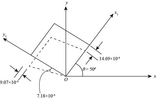
Figure (1)
Conclusion:
The normal strain along x direction is
The normal strain along y direction is
The shear strain along x-y plane is
(b)
The principal strains.
(b)
Answer to Problem 7.7.18P
The maximum principal strain is
Explanation of Solution
Write expression for the principal strains.
Here, the maximum principal strain is
Write the expression for the principal angle.
Here,
Calculation:
Substitute
While taking positive sign you get maximum principal strain:
While taking negative sign you get minimum principal strain.
Substitute
In below figure principal strains and principal angle are shown:
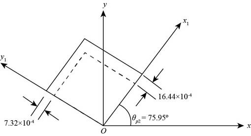
Figure (2)
Conclusion:
The maximum principal strain is
(c)
The maximum shear strain.
(c)
Answer to Problem 7.7.18P
The maximum shear strain is
Explanation of Solution
Write the expression for maximum shear strain,
Here,
Write expression for first shear angle
Here,
Write expression for second shear angle
Here,
Write the Equation for average strain
Write expression for maximum shear strain.
Calculation:
Substitute
Substitute
Substitute
Substitute
Substitute
In below figure average minimum strain and shear angle are shown:

Figure (3)
Conclusion:
The maximum shear strain is
Want to see more full solutions like this?
Chapter 7 Solutions
Mechanics of Materials (MindTap Course List)


- A spherical steel pressure vessel (diameter 500 mm, thickness 10 mm) is coated with brittle lacquer that cracks when the strain reaches 150 X 10~ (see figure). (a) What internal pressure p will cause the lacquer to develop cracks? (Assume E = 205 GPa and v = 0.30.) (b) If the strain is measured at 125 x 10-6, what is the internal pressure at that point?arrow_forwardSolve the preceding problem if the cube is granite (E = 80 GPa, v = 0.25) with dimensions E = 89 mm and compressive strains E = 690 X l0-6 and = = 255 X 10-6. For part (c) of Problem 7.6-5. find the maximum value of cr when the change in volume must be limited to 0.11%. For part. find the required value of when the strain energy must be 33 J.arrow_forwardSolve the preceding problem if the diameter is 480 mm, the pressure is 20 MPa, the yield stress in tension is 975 MPa, the yield stress in shear is 460 MPa, the factor of safety is 2,75, the modulus of elasticity is 210 GPa, Poissorfs ratio is 0.28, and the normal strain must not exceed 1190 x 10" . For part (b), assume that the tank thickness is 8 mm and the measured normal strain is 990 x 10~ .arrow_forward
- A flat bar of width b and thickness t has a hole of diameter d drilled through it (see figure). The hole may have any diameter that will fit within the bar. What is the maximum permissible tensile load Pmaxif the allowable tensile stress in the material is st?arrow_forwardA punch for making a slotted hole in ID cards is shown in the figure part a. Assume that the hole produced by the punch can be described as a rectangle (12 mm X 3 mm) with two half circles (r = 1.5 mm) on the left and the right sides. If P = 10 N and the thickness of the ID card is 1 mm, what is the average shear stress in the card?arrow_forwardRepeat Problem 2.3-18, but assume that the bar is made of copper alloy. Calculate the displacements SBand Scif P = 50 kips, L = 5 ft = 3/5 in., b1= 2.75 in., b2= 3 in., and E = 16,000 ksi.arrow_forward
- A solid circular bar of diameter d = 50 mm (see figure) is twisted in a testing maching until the applied torque reaches the value T = 500 N ·. At this value of torque, a strain gage oriented at 45º to the axis of the bar gives a reading e = 339 × 10-6. What is the shear modulus G of the material?arrow_forwardSolve the preceding problem for a plate of dimensions 100 mm × 250 mm subjected to a compressive stress of 2.5 MPa in the long direction and a tensile stress of 12.0 MPa in the short direction (see figure).arrow_forwardSolve the preceding problem if the element is steel (E = 200 GPa. p = 0.30) with dimensions a = 300 mm. h = 150 mm. and c = 150 mm a n d with the stresses (T( = —62 MPa, r. = -45 MPa, and = MPa. For part (e) of Problem 7.6-3, find the maximum value of u. if the change in volume must be limited to —0.028%. For part (0. find the required value of if the strain energy must be 60 J.arrow_forward
- A copper wire having a diameter ofd = 4 mm is bent into a circle and held with the ends just touching (see figure), If the maximum permissible strain in the copper is = 0.0024, what is the shortest length L of wire that can be used? If L = 5.5 m, what is the maximum acceptable diameter of the wire if the maximum normal strain must remain below yield? Assume E = 120 GPa and(7K= 300 MPa.arrow_forwardSolve the preceding problem for sx= 11 MPa and ??y= -20 MPa (see figure).arrow_forwardA standard brick (dimensions 8 in. × 4 in. × 2.5 in ) is compressed lengthwise by a force P. as shown in the figure, If the ultimate shear stress for brick is 1200 psi and the ultimate compressive stress is 3600 psi. what force Pmax is required to break the brick?arrow_forward
 Mechanics of Materials (MindTap Course List)Mechanical EngineeringISBN:9781337093347Author:Barry J. Goodno, James M. GerePublisher:Cengage Learning