
Videos
Knowing that the radius of each pulley is 120 mm and neglecting friction, determine the internal forces at (a) point C, (b) point J that is 100 mm to the left of C.
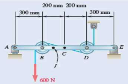
Fig. P7.15 and P7.16
(a)
The internal forces exerted at the point
Answer to Problem 7.15P
The internal forces of shearing force is
Explanation of Solution
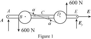
Sketch the free body diagram for the internal forces acting on the frame and pulley system as shown in the Figure 1.
Write the equation of the axial force exerted at the axial point
Here, the force exerted on the frame at the point
Write the equation of the moment of couple formed in the bending moment of the frame and pulley system supported at the point
Here, the axial force exerted on the pulley at point
Write the equation of the axial force exerted at the axial point of the frame from y direction (Refer fig 1).
Here, the axial force exerted on the pulley at point
Sketch the free body diagram for the cable as shown in the Figure 2.
The slope of the cable (Refer fig 2):
The angle formed in the slope of the cable:
Rewrite the above relation to find the angle.
Write the equation of the axial force exerted at the axial point
Here, the angle between the pulley
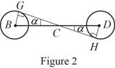
Sketch the free body diagram for the cable for the point
Write the equation of the axial force exerted at the point
Here, shearing force acting on the semicircular rod is
At the pulley
Write the equation of the moment of couple formed in the bending moment supported at the point
Here, the moment of couple exerted at the point
Conclusion:
Substitute
Solve the above equation for
Substitute
Substitute
Substitute
Substitute
The above equation can be written as,
Therefore, the internal forces of shearing force is
(b)
The internal forces exerted at the point
Answer to Problem 7.15P
The internal forces of shearing force is
Explanation of Solution
Sketch the free body diagram for the cable for the point
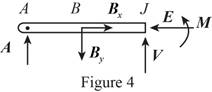
Write the equation of the axial force exerted at the axial point
Here, the force exerted on the frame at the point
Write the equation of the axial force exerted at the axial point of the frame from y direction (Refer fig 4).
Here, the axial force exerted on the pulley at point
Write the equation of the moment of couple formed in the bending moment supported at the point
Here, the moment of couple exerted at the point
Conclusion:
Substitute
Substitute
Substitute
The above equation can be written as,
Therefore, the internal forces of shearing force is
Want to see more full solutions like this?
Chapter 7 Solutions
Vector Mechanics for Engineers: Statics
Additional Engineering Textbook Solutions
DeGarmo's Materials and Processes in Manufacturing
Fundamentals of Heat and Mass Transfer
Fluid Mechanics Fundamentals And Applications
INTERNATIONAL EDITION---Engineering Mechanics: Statics, 14th edition (SI unit)
Thinking Like an Engineer: An Active Learning Approach (4th Edition)


- A 40-m cable is strung as shown between two buildings. The maximum tension is found to be 350 N, and the lowest point of the cable is observed to be 6 m above the ground. Determine (a) the horizontal distance between the buildings, (b) the total mass of the cable.arrow_forwardDetermine the value of w and P such that the resultant of the system is a downward force of magnitude 1200 N acting 3.6 m to the right of A. Determine the magnitude of the uniform load w. a.252 N/m b.646.1 N/m c.387.7 N/m d.553.8 N/marrow_forwardDetermine the sag of a 30-ft chain that is attached to two points at the same elevation that are 20 ft apart.arrow_forward
- A cable is placed around three parallel pipes. Two of the pipes are fixed and do not rotate; the third pipe is slowly rotated. Knowing that the coefficients of friction are μs= 0.25 and μk= 0.20, determine the largest weight W that can be raised (a) if only pipe A is rotated counterclockwise, (b) if only pipe C is rotated clockwise.arrow_forwardA single-acting cylinder working in traction under a pressure of60 psig has a return spring with a force of 15 lbs. Knowing that the diameter ofthe rod is ¼ in. and that of the piston is 1 in., what is the force developedby this cylinder? [Answer:29.4 lbs]arrow_forwardThe center span of the Verrazano-Narrows Bridge consists of two uniform roadways suspended from four cables. The design of the bridge allows for the effect of extreme temperature changes that cause the sag of the center span to vary from hw= 386 ft in winter to hs= 394 ft in summer. Knowing that the span is L = 4260 ft, determine the change in length of the cables due to extreme temperature changes.arrow_forward
- A steam pipe weighing 45 lb/ft that passes between two buildings 40 ft apart is supported by a system of cables as shown. Assuming that the weight of the cable system is equivalent to a uniformly distributed loading of 5 lb/ft, determine (a) the location of the lowest point C of the cable, (b) the maximum tension in the cable.arrow_forwardA cable AB of span L and a simple beam A'B' of the same span are subjected to identical vertical loadings as shown. Show that the magnitude of the bending moment at a point C' in the beam is equal to the product T0h, where T0 is the magnitude of the horizontal component of the tension force in the cable and h is the vertical distance between point C and the chord joining the points of support A and B.arrow_forwardA flat belt connects pulley a, which drives a machine tool, to pulley b, which is attached to the shaft of an electric motor. the coefficients of friction are μs = 0.25 and μk = 0.20 between both pulleys and the belt. knowing that the maximum allowable tension in the belt is 600 lb, determine the largest torque that the belt can exert on pulley aarrow_forward
- The uniform 10 kg rod AB is supported by a ball and socket joint at A and by the cord CG that is attached to the midpoint G of the rod. Knowing that the rod leans against a frictionless vertical wall at B and that the tension in the cord CG, TCG=52.1 N, determine the following, Which of the following best approximates the moment of the weight of the structure about A? Choices: (7.36i + 29.4k) N-m(7.36i + 29.4j) N-m(29.4i + 7.36k) N-m(29.4i + 7.36j) N-marrow_forwardA farmer uses cables and winch pullers B and E to plumb one side of a small barn. If it is known that the sum of the moments about the X axis of the forces exerted by the cables on the barn at points A and D is equal to 4728 lb·ft, determine the magnitude of TDE when TAB = 255 lb.arrow_forwardA farmer uses cables and winch pullers B and E to plumb one side of a small barn. If it is known that the sum of the moments about the x axis of the forces exerted by the cables on the barn at points A and D is equal to 4728 lb·ft, determine the magnitude of TDE when TAB=255 lb.arrow_forward
 Elements Of ElectromagneticsMechanical EngineeringISBN:9780190698614Author:Sadiku, Matthew N. O.Publisher:Oxford University Press
 Mechanics of Materials (10th Edition)Mechanical EngineeringISBN:9780134319650Author:Russell C. HibbelerPublisher:PEARSON
 Thermodynamics: An Engineering ApproachMechanical EngineeringISBN:9781259822674Author:Yunus A. Cengel Dr., Michael A. BolesPublisher:McGraw-Hill Education
 Control Systems EngineeringMechanical EngineeringISBN:9781118170519Author:Norman S. NisePublisher:WILEY
 Mechanics of Materials (MindTap Course List)Mechanical EngineeringISBN:9781337093347Author:Barry J. Goodno, James M. GerePublisher:Cengage Learning
 Engineering Mechanics: StaticsMechanical EngineeringISBN:9781118807330Author:James L. Meriam, L. G. Kraige, J. N. BoltonPublisher:WILEY