
Videos
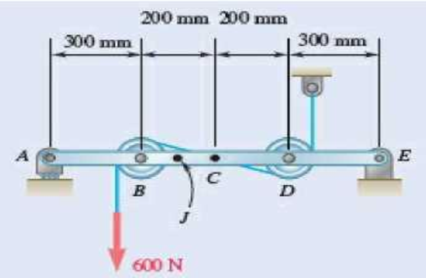
Fig. P7.15 and P7.16
7.16 Knowing that the radius of each pulley is 100 mm and neglecting friction, determine the internal forces at (a) point C, (b) point J that is 100 mm to the left of C.
(a)
The internal forces exerted at the point
Answer to Problem 7.16P
The internal forces of shearing force is
Explanation of Solution
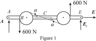
Sketch the free body diagram for the internal forces acting on the frame and pulley system as shown in the Figure 1.
Write the equation of the axial force exerted at the axial point
Here, the force exerted on the frame at the point
Write the equation of the moment of couple formed in the bending moment of the frame and pulley system supported at the point
Here, the axial force exerted on the pulley at point
Write the equation of the axial force exerted at the axial point of the frame from y direction (Refer fig 1).
Here, the axial force exerted on the pulley at point
Sketch the free body diagram for the cable as shown in the Figure 2.
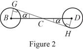
The slope of the cable (Refer fig 2):
The angle formed in the slope of the cable:
Write the equation of the axial force exerted at the axial point
Here, the angle between the pulley
Sketch the free body diagram for the cable for the point
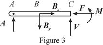
Write the equation of the axial force exerted at the point
Here, shearing force acting on the semicircular rod is
At the pulley
Write the equation of the moment of couple formed in the bending moment supported at the point
Here, the moment of couple exerted at the point
Conclusion:
Substitute
Solve the above equation for
Substitute
Substitute
Substitute
Substitute
The above equation can be written as,
Therefore, The internal forces of shearing force is
(b)
The internal forces exerted at the point
Answer to Problem 7.16P
The internal forces of shearing force is
Explanation of Solution
Sketch the free body diagram for the cable for the point
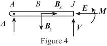
Write the equation of the axial force exerted at the axial point
Here, the force exerted on the frame at the point
Write the equation of the axial force exerted at the axial point of the frame from y direction (Refer fig 4).
Here, the axial force exerted on the pulley at point
Write the equation of the moment of couple formed in the bending moment supported at the point
Here, the moment of couple exerted at the point
Conclusion:
Substitute
Substitute
Substitute
The above equation can be written as,
Therefore, the internal forces of shearing force is
Want to see more full solutions like this?
Chapter 7 Solutions
Vector Mechanics for Engineers: Statics and Dynamics


- A block with weight W is pulled up a plane forming an angle a with the horizontal by a force P directed along the plane. μ If is the coefficient of friction between the block and the plane, derive an expression for the mechanical efficiency of the system. Show that the mechanical efficiency cannot exceed 1/2 if the block is to remain in place when the force P is removed.arrow_forwardA 40-m cable is strung as shown between two buildings. The maximum tension is found to be 350 N, and the lowest point of the cable is observed to be 6 m above the ground. Determine (a) the horizontal distance between the buildings, (b) the total mass of the cable.arrow_forwardA flat belt is used to transmit a couple from pulley A to pulley B . The radius of each pulley is 60 mm, and a force of magnitude P = 900 N is applied as shown to the axle of pulley A . Knowing that the coefficient of static friction is 0.35, determine (a) the largest couple that can be transmitted, (b) the corresponding maximum value of the tension in the belt.arrow_forward
- A cable is placed around three parallel pipes. Two of the pipes are fixed and do not rotate; the third pipe is slowly rotated. Knowing that the coefficients of friction are μs= 0.25 and μk= 0.20, determine the largest weight W that can be raised (a) if only pipe A is rotated counterclockwise, (b) if only pipe C is rotated clockwise.arrow_forwardA cable AB of span L and a simple beam A'B' of the same span are subjected to identical vertical loadings as shown. Show that the magnitude of the bending moment at a point C' in the beam is equal to the product T0h, where T0 is the magnitude of the horizontal component of the tension force in the cable and h is the vertical distance between point C and the chord joining the points of support A and B.arrow_forwardA steam pipe weighing 45 lb/ft that passes between two buildings 40 ft apart is supported by a system of cables as shown. Assuming that the weight of the cable system is equivalent to a uniformly distributed loading of 5 lb/ft, determine (a) the location of the lowest point C of the cable, (b) the maximum tension in the cable.arrow_forward
- A 15° wedge is forced into a saw cut to prevent binding of the circular saw. The coefficient of static friction between the wedge and the wood is 0.25. Knowing that a horizontal force P with a magnitude of 30 lb was required to insert the wedge, determine the magnitude of the forces exerted on the board by the wedge after insertion.arrow_forwardA farmer uses cables and winch pullers B and E to plumb one side of a small barn. If it is known that the sum of the moments about the x axis of the forces exerted by the cables on the barn at points A and D is equal to 4728 lb·ft, determine the magnitude of TDE when TAB=255 lb.arrow_forwardA farmer uses cables and winch pullers B and E to plumb one side of a small barn. If it is known that the sum of the moments about the X axis of the forces exerted by the cables on the barn at points A and D is equal to 4728 lb·ft, determine the magnitude of TDE when TAB = 255 lb.arrow_forward
- Pin B weighs 0.1kg and is free to slide in a horizontal plane along therotating arm OC and along the circular slot DE of radius b=500mm.Neglecting friction and assuming that θ= 15 rad/s andθ=250 rad/s2 for the position θ= 20o , determine for that position(a) the radial and transverse components of the resultant forceexerted on pin B, (b) the forces P and Q exerted on pin B,respectively, by rod OC and the wall of slot DE.arrow_forwardA 12° wedge is used to spread a split ring. The coefficient of static friction between the wedge and the ring is 0.30. Knowing that a force P with a magnitude of 120 N was required to insert the wedge, determine the magnitude of the forces exerted on the ring by the wedge after insertion.arrow_forwardA band belt is used to control the speed of a flywheel as shown. Determine the magnitude of the couple being applied to the flywheel, knowing that the coefficient of kinetic friction between the belt and the flywheel is 0.25 and that the flywheel is rotating clockwise at a constant speed. Show that the same result is obtained if the flywheel rotates counterclockwise.arrow_forward
 Elements Of ElectromagneticsMechanical EngineeringISBN:9780190698614Author:Sadiku, Matthew N. O.Publisher:Oxford University Press
 Mechanics of Materials (10th Edition)Mechanical EngineeringISBN:9780134319650Author:Russell C. HibbelerPublisher:PEARSON
 Thermodynamics: An Engineering ApproachMechanical EngineeringISBN:9781259822674Author:Yunus A. Cengel Dr., Michael A. BolesPublisher:McGraw-Hill Education
 Control Systems EngineeringMechanical EngineeringISBN:9781118170519Author:Norman S. NisePublisher:WILEY
 Mechanics of Materials (MindTap Course List)Mechanical EngineeringISBN:9781337093347Author:Barry J. Goodno, James M. GerePublisher:Cengage Learning
 Engineering Mechanics: StaticsMechanical EngineeringISBN:9781118807330Author:James L. Meriam, L. G. Kraige, J. N. BoltonPublisher:WILEY